Subaru Crosstrek Service Manual: Assembly
BRAKE > Rear Disc Brake Assembly
ASSEMBLY
1. Before installation, check each part. Rear Disc Brake Assembly > INSPECTION">
2. Clean the inside of the caliper body cylinder using brake fluid.
3. Apply a coat of brake fluid to piston seal and install the piston seal to the caliper body cylinder groove.
4. Apply a coat of brake fluid to the inner surface of caliper body cylinder and the entire outer surface of the piston - disc brake.
5. Apply grease contained in the piston seal kit to the piston boot, and install it to the groove at the end of the cylinder.
6. Insert the piston - disc brake into the caliper body cylinder.
CAUTION:
Do not force the piston - disc brake into the caliper body cylinder.
7. Position the piston boot in the grooves on the piston - disc brake and the caliper body cylinder.
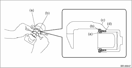
(a) | Piston - disc brake | (c) | Caliper body | (d) | Piston seal |
(b) | Piston boot |
8. Apply grease contained in the piston seal kit to the lock pin - rear brake, the outer surface of guide pin - rear brake, the inner surface of support cylinder, and the grooves of pin boot.
9. Install the pin boot to the lock pin - rear brake and guide pin - rear brake, and insert them into the support cylinder.
CAUTION:
Insert the lock pin - rear brake and guide pin - rear brake into specified position, and make sure that they slide and seat properly.

(a) | Pin boot | (b) | Lock pin - rear brake or guide pin - rear brake | (c) | Grease applied area |

 Removal
BRAKE > Rear Disc Brake AssemblyREMOVALCAUTION:Do not allow brake fluid to come in contact with the painted surface of the vehicle body. If it does, wash off with water and wipe away completely.1. ...
Other materials:
Dtc c1232 rear right abs sensor signal
VEHICLE DYNAMICS CONTROL (VDC) (DIAGNOSTICS) > Diagnostic Procedure with Diagnostic Trouble Code (DTC)DTC C1232 REAR RIGHT ABS SENSOR SIGNALNOTE:For the diagnostic procedure, refer to “DTC C1242 REAR LEFT ABS SENSOR SIGNAL”. Diagnostic Procedure with Diagnostic Trouble Code (DTC) > ...
Viewing range on the screen
CAUTION
The range that can be viewed with
the rear view camera is limited.
Always be sure to check with your
eyes when moving backward and
proceed slowly.
Range of view
Range of view
Image from camera
The area from the rear end of the bumper
can be viewed. Areas at both ends ...
Removal
CONTINUOUSLY VARIABLE TRANSMISSION(TR580) > Reduction Drive GearREMOVAL1. Remove the transmission assembly from the vehicle. Automatic Transmission Assembly > REMOVAL">2. Remove the air breather hose. Air Breather Hose > REMOVAL">3. Remove the control valve body. Control ...
