Subaru Crosstrek Service Manual: Assembly
BRAKE > Front Disc Brake Assembly
ASSEMBLY
1. Before assembly, check each part. Front Disc Brake Assembly > INSPECTION">
2. Clean the inside of the caliper body cylinder using brake fluid.
3. Apply a coat of brake fluid to piston seal and install the piston seal to the caliper body cylinder groove.
4. Apply a coat of brake fluid to the inner surface of caliper body cylinder and the entire outer surface of the piston - disc brake.
5. Apply grease contained in the piston seal kit to the piston boot, and install it to the groove at the end of the cylinder.
6. Insert the piston - disc brake into the caliper body cylinder.
7. Position the piston boot in the grooves on the piston - disc brake and the caliper body cylinder.
CAUTION:
Do not force the piston - disc brake into the caliper body cylinder.
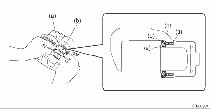
(a) | Piston - disc brake | (c) | Caliper body assembly | (d) | Piston seal |
(b) | Piston boot |
8. Apply grease contained in the piston seal kit to the lock pin - front brake, the outer surface of guide pin - front brake, the inner surface of support cylinder, and the grooves of pin boot.
9. Install the pin boot to the lock pin - front brake and guide pin - front brake, and insert them into the support cylinder.
CAUTION:
Insert the lock pin - front brake and guide pin - front brake into specified position, and make sure that they slide and seat properly.
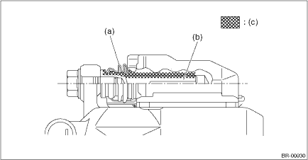
(a) | Pin boot | (b) | Lock pin - front brake or guide pin - front brake | (c) | Grease applied area |

 Removal
BRAKE > Front Disc Brake AssemblyREMOVALCAUTION:Do not allow brake fluid to come in contact with the painted surface of the vehicle body. If it does, wash off with water and wipe away completely.1. ...
Other materials:
Dtc c1232 rear right abs sensor signal
VEHICLE DYNAMICS CONTROL (VDC) (DIAGNOSTICS) > Diagnostic Procedure with Diagnostic Trouble Code (DTC)DTC C1232 REAR RIGHT ABS SENSOR SIGNALNOTE:For the diagnostic procedure, refer to “DTC C1242 REAR LEFT ABS SENSOR SIGNAL”. Diagnostic Procedure with Diagnostic Trouble Code (DTC) > ...
Read cancel code Operation
CRUISE CONTROL SYSTEM (DIAGNOSTICS) > Read Cancel CodeOPERATION1. On «Start» display, select «Diagnosis».2. On «Vehicle selection» display, input the target vehicle information and select «Confirmed».3. On «Main Menu» display, select «Each System».4. On «Select System» display, sele ...
Installation
CLUTCH SYSTEM > Operating CylinderINSTALLATION1. Install in the reverse order of removal.NOTE:• Before installing the operating cylinder, apply grease to the contact point of the release lever and operating cylinder.Grease:NICHIMOLY N-130 or equivalent• Be sure to install the clutch h ...
