Subaru Crosstrek Service Manual: Antenna cord Location
WIRING SYSTEM > Antenna Cord
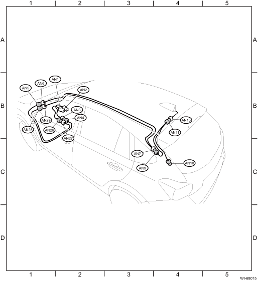
LOCATION
1. WITHOUT TELEMATICS
Connector | Connecting to | ||||
No. | Pole | Color | Area | No. | Description |
AN1 | 3 |
| B-2 | Audio | |
3 |
| B-2 | Navigation unit | ||
AN2 | 1 |
| B-2 | Audio | |
1 |
| B-2 | Navigation unit | ||
AN3 | 1 |
| B-2 | AN4 | Antenna cord |
AN4 | 1 |
| B-2 | AN3 | |
AN5 | 1 |
| B-1 | AN6 | |
AN6 | 1 |
| B-1 | AN5 | |
AN7 | 3 |
| C-3 | AN9 | |
AN9 | 3 |
| C-4 | AN7 | |
AN10 | 1 |
| C-4 | R97 | |
AN11 | 3 |
| B-4 | AN15 | Antenna |
AN15 | 3 |
| B-4 | AN11 | Antenna cord |
AN26 | 3 |
| B-2 | AN27 | |
AN27 | 3 | Gray | B-2 | AN26 | |
AN28 | 3 |
| B-1 | AN29 | |
AN29 | 3 |
| B-1 | AN28 | |
| |||||

2. WITH TELEMATICS
Connector | Connecting to | ||||
No. | Pole | Color | Area | No. | Description |
AN1 | 3 |
| B-2 | Audio | |
3 |
| B-2 | Navigation unit | ||
AN2 | 1 |
| B-2 | Audio | |
1 |
| B-2 | Navigation unit | ||
AN3 | 3 |
| B-2 | AN4 | Antenna cord |
AN4 | 3 |
| B-2 | AN3 | |
AN5 | 3 |
| B-1 | AN6 | |
AN6 | 3 |
| B-1 | AN5 | |
AN7 | 3 | Blue | C-3 | AN9 | |
AN9 | 3 |
| C-3 | AN7 | |
AN10 | 1 |
| C-4 | R97 | |
AN11 | 3 |
| B-4 | AN15 | Antenna |
AN15 | 3 |
| B-4 | AN11 | Antenna cord |
AN19 | 1 |
| B-2 | Data communication module | |
AN20 | 1 |
| B-2 | AN21 | Antenna cord |
AN21 | 1 |
| B-2 | AN20 | |
AN22 | 1 |
| B-1 | AN23 | |
AN23 | 1 |
| B-1 | AN22 | |
AN24 | 1 |
| B-4 | AN25 | Telematics antenna |
AN25 | 1 |
| B-4 | AN24 | Antenna cord |
| |||||
Connector | Connecting to | ||||
No. | Pole | Color | Area | No. | Description |
AD1 | 8 |
| B-1 | B229 | Bulkhead wiring harness |
AD2 | 8 |
| B-2 | Telematics button | |
| |||||

 Airbag system Wiring diagram
WIRING SYSTEM > Airbag SystemWIRING DIAGRAM ...
 Audio system Wiring diagram
WIRING SYSTEM > Audio SystemWIRING DIAGRAM1. 6.2-INCH DISPLAY2. 7 INCH DISPLAY (WITHOUT TELEMATICS)3. 7 INCH DISPLAY (WITH TELEMATICS) ...
Other materials:
Removal
BRAKE > Stop Light SwitchREMOVALCAUTION:Before handling the airbag system components, always refer to “CAUTION” of “General Description” in “AIRBAG SYSTEM”. General Description > CAUTION">1. Disconnect the ground cable from battery and wait for at l ...
If you park your vehicle in case of an emergency
Models with multi function display
Models without multi function display
The hazard warning flasher should be
used in day or night to warn other drivers
when you have to park your vehicle under
emergency conditions.
Avoid stopping on the road. It is best to
safely pull off the roa ...
Installation
POWER ASSISTED SYSTEM (POWER STEERING) > Universal JointINSTALLATION1. Before installation, check the universal joint assembly - steering. Universal Joint > INSPECTION">2. Adjust the tilt position of the column assembly - steering to the neutral position and lock the tilt lever.3. Ali ...
