Subaru Crosstrek Service Manual: 11
CRUISE CONTROL SYSTEM (DIAGNOSTICS) > Diagnostic Procedure with Cancel Code
11
When CRUISE switch is pressed, or a malfunction related to CRUISE switch occurs, this is detected.
Trouble symptom:
• Cruise control cannot be set. (Cancelled immediately.)
• Cruise control cannot be released.
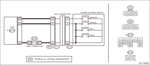
Wiring diagram:
Cruise control system Cruise Control System > WIRING DIAGRAM">
| STEP | CHECK | YES | NO |
1.CHECK CRUISE CONTROL COMMAND SWITCH CIRCUIT.
1) Remove the driver’s airbag module. Driver’s Airbag Module > REMOVAL">
2) Disconnect the harness connector of cruise control command switch.
3) Turn the ignition switch to ON.
4) Measure the voltage between harness connector terminal and chassis ground.
Connector & terminal
(ST3) No. 4 (+) — Chassis ground (−):
(ST3) No. 3 (+) — Chassis ground (−):
Is the voltage 5 V or more?
Diagnostic Procedure with Cancel Code > 11">Go to Step 2.
Check the harness between cruise control command switch and ECM, and the steering roll connector for open or short circuit, or for poor contact.
2.CHECK CRUISE CONTROL COMMAND SWITCH CIRCUIT.
1) Turn the ignition switch to OFF.
2) Remove the cruise control command switch. Cruise Control Command Switch > REMOVAL">
3) Measure the resistance between harness connector terminal and chassis ground.
Connector & terminal
(ST3) No. 9 — Chassis ground:
Is the resistance less than 10 ??
Diagnostic Procedure with Cancel Code > 11">Go to Step 3.
Check for open circuit between cruise control command switch, ECM, and chassis ground and check the ECM.
3.CHECK CRUISE CONTROL COMMAND SWITCH.
Measure the resistance between switch terminals when the cruise control command switch is not depressed.
Terminals
No. 3 — No. 9:
Is the resistance approx. 4 k??
Diagnostic Procedure with Cancel Code > 11">Go to Step 4.
Replace the cruise control command switch.
Cruise Control Command Switch">
4.CHECK CANCEL SWITCH.
1) Turn the ignition switch to OFF.
2) Remove the cruise control command switch. Cruise Control Command Switch > REMOVAL">
3) Measure the resistance between switch terminals with the CANCEL switch pressed.
Terminals
No. 3 — No. 9:
Is the resistance approx. less than 1 ? when the CANCEL switch is pressed?
Diagnostic Procedure with Cancel Code > 11">Go to Step 5.
Replace the cruise control command switch.
Cruise Control Command Switch">
5.CHECK SET/− SWITCH.
Measure the resistance between the switch terminals with the SET/− switch pressed.
Terminals
No. 3 — No. 9:
Is the resistance approx. 250 ? when the SET/− switch is pressed?
Diagnostic Procedure with Cancel Code > 11">Go to Step 6.
Replace the cruise control command switch. Cruise Control Command Switch">
6.CHECK RES/+ SWITCH CIRCUIT.
Measure the resistance between the switch terminals with the RES/+ switch pressed.
Terminals
No. 3 — No. 9:
Is the resistance approx. 1,500 ? when the RES/+ switch is pressed?
Replace the ECM.
Engine Control Module (ECM)">
Replace the cruise control command switch. Cruise Control Command Switch">

 49
49
CRUISE CONTROL SYSTEM (DIAGNOSTICS) > Diagnostic Procedure with Cancel Code49Automatic transmission malfunction is detected.Automatic transmission malfunction is detected during cruise driving or c ...
Other materials:
Component
IGNITION(H4DO) > General DescriptionCOMPONENT(1)Spark plug(2)Ignition coilTightening torque: N·m (kgf-m, ft-lb) T1:8.5 (0.9, 6.3) T2:17.5 (1.8, 12.9) ...
Dtc c2322 transmitter 2 function code abnormal
TIRE PRESSURE MONITORING SYSTEM (DIAGNOSTICS) > Diagnostic Procedure with Diagnostic Trouble Code (DTC)DTC C2322 TRANSMITTER 2 FUNCTION CODE ABNORMALNOTE:Refer to DTC C2324 for diagnostic procedure. Diagnostic Procedure with Diagnostic Trouble Code (DTC) > DTC C2324 TRANSMITTER 4 FUNCTION COD ...
How to change the source
The USB Audio playback screen can be
reached by the following methods:
Connect a USB memory. Refer to
"Connecting and disconnecting a USB
memory/portable device"
Select the "USB/iPod" key on the
source select screen. Refer to "Selecting
an audio source"
Select play mode
The play m ...
