Subaru Crosstrek Service Manual: Dtc c1711 steering angle sensor
VEHICLE DYNAMICS CONTROL (VDC) (DIAGNOSTICS) > Diagnostic Procedure with Diagnostic Trouble Code (DTC)
DTC C1711 STEERING ANGLE SENSOR
DTC detecting condition:
Defective steering angle sensor
Trouble symptom:
• ABS does not operate.
• VDC does not operate.
• Hill start assist does not operate.
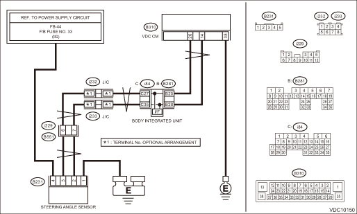
Wiring diagram:
Vehicle dynamics control system Vehicle Dynamics Control System > WIRING DIAGRAM">
| STEP | CHECK | YES | NO |
1.CHECK POWER SUPPLY FOR STEERING ANGLE SENSOR.
1) Turn the ignition switch to OFF.
2) Disconnect the connector from steering angle sensor.
3) Turn the ignition switch to ON.
4) Measure the voltage between steering angle sensor and chassis ground.
Connector & terminal
(B231) No. 4 (+) — Chassis ground (−):
Is the voltage 10 — 15 V?
Diagnostic Procedure with Diagnostic Trouble Code (DTC) > DTC C1711 STEERING ANGLE SENSOR">Go to Step 2.
Repair the steering angle sensor power supply circuit including the fuse.
2.CHECK GROUND CIRCUIT OF STEERING ANGLE SENSOR (CHECK FOR OPEN CIRCUIT).
Measure the resistance between steering angle sensor and chassis ground.
Connector & terminal
(B231) No. 1 — Chassis ground:
Is the resistance less than 10 ??
Diagnostic Procedure with Diagnostic Trouble Code (DTC) > DTC C1711 STEERING ANGLE SENSOR">Go to Step 3.
Repair ground circuit in the steering angle sensor.
3.CHECK STEERING ANGLE SENSOR HARNESS (CHECK FOR OPEN CIRCUIT).
1) Disconnect the connector from the VDCCM&H/U.
2) Measure the resistance between VDCCM&H/U and steering angel sensor.
Connector & terminal
(B231) No. 2 — (B310) No. 14:
(B231) No. 3 — (B310) No. 26:
Is the resistance less than 1 ??
Diagnostic Procedure with Diagnostic Trouble Code (DTC) > DTC C1711 STEERING ANGLE SENSOR">Go to Step 4.
Repair the harness between the steering angle sensor and VDCCM&H/U.
4.CHECK GROUND SHORT CIRCUIT OF STEERING ANGLE SENSOR HARNESS.
Measure the resistance between steering angle sensor and chassis ground.
Connector & terminal
(B231) No. 2 — Chassis ground:
(B231) No. 3 — Chassis ground:
Is the resistance 10 ? or more?
Diagnostic Procedure with Diagnostic Trouble Code (DTC) > DTC C1711 STEERING ANGLE SENSOR">Go to Step 5.
Repair the harness between the steering angle sensor and VDCCM&H/U.
5.CHECK STEERING WHEEL.
1) Drive the vehicle on a flat road.
2) Park the vehicle straight.
3) Check the steering wheel for deviation from center.
Is the deviation from the center of steering wheel less than 5°?
Diagnostic Procedure with Diagnostic Trouble Code (DTC) > DTC C1711 STEERING ANGLE SENSOR">Go to Step 6.
Perform the centering adjustment of steering wheel, and perform the VDC sensor midpoint setting mode. VDC Control Module and Hydraulic Control Unit (VDCCM&H/U) > ADJUSTMENT">
6.CHECK OUTPUT OF STEERING ANGLE SENSOR USING SUBARU SELECT MONITOR.
1) Adjust steering wheel to the center position.
2) Using the Subaru Select Monitor, select “Data monitor”. Subaru Select Monitor > OPERATION">
3) Read the «Steering Angle Sensor» displayed on display.
Is the reading of «Steering Angle Sensor» −10° — 10°?
Perform the VDC sensor midpoint setting mode. VDC Control Module and Hydraulic Control Unit (VDCCM&H/U) > ADJUSTMENT">
Diagnostic Procedure with Diagnostic Trouble Code (DTC) > DTC C1711 STEERING ANGLE SENSOR">Go to Step 7.
Check the installation of the steering wheel and steering angle sensor.
7.CHECK VDCCM&H/U.
1) Turn the ignition switch to OFF.
2) Connect all connectors.
3) Perform the Clear Memory Mode. Clear Memory Mode">
4) Perform the Inspection Mode. Inspection Mode">
5) Read the DTC. Read Diagnostic Trouble Code (DTC)">
Is the same DTC displayed?
Replace the steering angle sensor. Steering Angle Sensor">
Diagnostic Procedure with Diagnostic Trouble Code (DTC) > DTC C1711 STEERING ANGLE SENSOR">Go to Step 8.
8.CHECK DETECTION OF OTHER DTCS FOR VDC.
Read Diagnostic Trouble Code (DTC)">
Is any other DTC displayed?
Perform the diagnosis according to DTC. List of Diagnostic Trouble Code (DTC)">
Currently, it is normal. There may have been a temporary poor contact in the harness and connector or a temporary noise interference.
 Dtc c1532 bls on stuck
VEHICLE DYNAMICS CONTROL (VDC) (DIAGNOSTICS) > Diagnostic Procedure with Diagnostic Trouble Code (DTC)DTC C1532 BLS ON STUCKDTC detecting condition:Defective stop light switchTrouble symptom:• ...
 Dtc c1721 yaw rate sensor
VEHICLE DYNAMICS CONTROL (VDC) (DIAGNOSTICS) > Diagnostic Procedure with Diagnostic Trouble Code (DTC)DTC C1721 YAW RATE SENSORDTC DETECTING CONDITION:Defective yaw rate & G sensorTROUBLE SYMPT ...
Other materials:
Cruise control (if equipped)
NOTE
For models with EyeSight system:
Refer to the Owner's Manual supplement
for the EyeSight system.
Cruise control enables you to maintain a
constant vehicle speed without holding
your foot on the accelerator pedal and it is
operative when the vehicle speed is 25
mph (40 km/h) or more.
WA ...
Adjustment
COOLING(H4DO) > Engine CoolantADJUSTMENT1. PROCEDURE TO ADJUST THE SUBARU SUPER COOLANT CONCENTRATIONCAUTION:Use the SUBARU Super Coolant with a 50 — 60% concentration in order to obtain maximum anti-freeze and anti-rust performance.To adjust the concentration of SUBARU Super Coolant according ...
Dtc c1424 ecm
VEHICLE DYNAMICS CONTROL (VDC) (DIAGNOSTICS) > Diagnostic Procedure with Diagnostic Trouble Code (DTC)DTC C1424 ECMDTC detecting condition:ECM malfunctioningTrouble symptom:• ABS does not operate.• VDC does not operate.• Hill start assist does not operate.STEPCHECKYESNO1.CHECK E ...
