Subaru Crosstrek Service Manual: System block diagram
TELEMATICS SYSTEM (DIAGNOSTICS) > Control Module I/O Signal
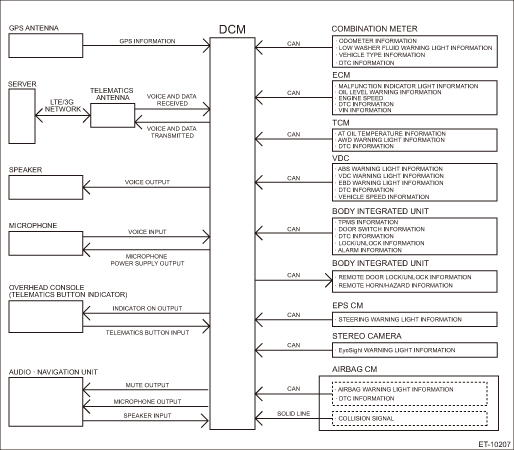
SYSTEM BLOCK DIAGRAM
Main signals used between DCM and relevant CM
 Wiring diagram
TELEMATICS SYSTEM (DIAGNOSTICS) > Control Module I/O SignalWIRING DIAGRAMRefer to “TELEMATICS SYSTEM” in the wiring diagram. Telematics System > WIRING DIAGRAM"> ...
 Specification
TELEMATICS SYSTEM (DIAGNOSTICS) > Control Module I/O SignalSPECIFICATION1. DATA COMMUNICATION MODULE (DCM)Terminal No.ContentMeasuring conditionStandardA1 — — — A2 — — — A3LED GREEN ...
Other materials:
Air conditioning system Wiring diagram
WIRING SYSTEM > Air Conditioning SystemWIRING DIAGRAM1. MANUAL A/C MODEL2. AUTO A/C MODEL ...
Removal
AIRBAG SYSTEM > Front Sub SensorREMOVALCAUTION:Before handling the airbag system components, refer to “CAUTION” of “General Description” in “AIRBAG SYSTEM”. General Description > CAUTION">1. Turn the ignition switch to OFF.2. Disconnect the ground c ...
Electrical component location Location
POWER ASSISTED SYSTEM (POWER STEERING) (DIAGNOSTICS) > Electrical Component LocationLOCATION(1)Steering gearbox(3)STEERING warning light(5)VDCCM&H/U(2)Power steering control module(4)Engine control module (ECM)(6)Data link connector (for Subaru Select Monitor)• U5 and U6 models• C ...
