Subaru Crosstrek Service Manual: Specification
TELEMATICS SYSTEM (DIAGNOSTICS) > Control Module I/O Signal
SPECIFICATION
1. DATA COMMUNICATION MODULE (DCM)
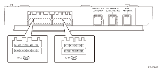
Terminal No. | Content | Measuring condition | Standard |
A1 | — | — | — |
A2 | — | — | — |
A3 | LED GREEN | — | — |
A4 ←> Chassis ground | i-button | i-button OFF > ON | 1.6 k? or more > less than 1 ? |
A5 ←> Chassis ground | SOS button | SOS button OFF > ON | 1.6 k? or more > less than 1 ? |
A6 | — | — | — |
A7 | CAN L | — | — |
A8 | Ignition power supply | Ignition switch OFF > ON | Less than 1 V > 9 — 16 V |
A9 | — | — | — |
A10 | Battery power supply | Always | 9 — 16 V |
A11 | — | — | — |
A12 | — | — | — |
A13 | LED RED | — | — |
A14 ←> Chassis ground | GND | Always | Less than 1 ? |
A15 | — | — | — |
A16 | — | — | — |
A17 | CAN H | — | — |
A18 | Airbag communication line | — | — |
A19 | MUTE | — | — |
A20 ←> Chassis ground | ACC | Ignition switch OFF > ACC ON | Less than 1 V > 9 — 16 V |
B1 | Front speaker input LH − | — | — |
B2 | Front speaker output LH − | — | — |
B3 | Front speaker input RH − | — | — |
B4 | Front speaker output RH − | — | — |
B5 | MIC signal OUT | — | — |
B6 | MIC signal | — | — |
B7 | MIC DET | — | — |
B8 | MIC 5 V | — | — |
B9 | Front speaker input LH + | — | — |
B10 | Front speaker output LH + | — | — |
B11 | Front speaker input RH + | — | — |
B12 | Front speaker output RH + | — | — |
B13 ←> Chassis ground | MIC GND OUT | Always | Less than 1 ? |
B14 | MIC GND IN | — | — |
B15 | — | — | — |
B16 | — | — | — |
 System block diagram
TELEMATICS SYSTEM (DIAGNOSTICS) > Control Module I/O SignalSYSTEM BLOCK DIAGRAMMain signals used between DCM and relevant CM ...

Other materials:
Note
LIGHTING SYSTEM > Turn Signal Light and Hazard Light SystemNOTEFor operation procedures of each component of the turn signal and hazard light system, refer to the respective sections.• Combination switch (light): Combination Switch (Light)">• Front turn signal light bulb: Fr ...
GVWR and GAWR (Gross Vehicle Weight Rating and Gross Axle Weight
Rating)
Certification label
The certification label attached to the
bottom of driver's side door pillar shows
GVWR (Gross Vehicle Weight Rating) and
GAWR (Gross Axle Weight Rating).
The GVW (Gross Vehicle Weight) must
never exceed the GVWR. GVW is the
combined total of weight of the vehicle,
f ...
How to read wiring diagrams
WIRING SYSTEM > Basic Diagnostic ProcedureHOW TO READ WIRING DIAGRAMS1. WIRING DIAGRAMThe wiring diagram of each system is illustrated so that you can understand the path through which the electric current flows from the battery.Sketches and codes are used in the diagrams. They should read as fol ...
