Subaru Crosstrek Service Manual: Service diagnostics mode Operation
ENTERTAINMENT > Service Diagnostics Mode
OPERATION
NOTE:
Installed only to model with 7 inch display.
1. PROCEDURE TO SWITCH TO SERVICE DIAGNOSTICS MODE
1. Turn the ignition switch to ACC.
2. After turning the ignition switch to ACC and wait for 20 seconds or more, press the button (b) five times with the button (a) pressed.
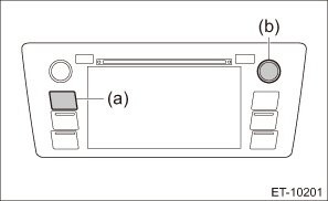
NOTE:
Pressing the button (a) for 3 seconds or more, or turning the ignition switch from the OFF to ACC position can exit the diagnostic mode.
2. SERVICE INSPECTION
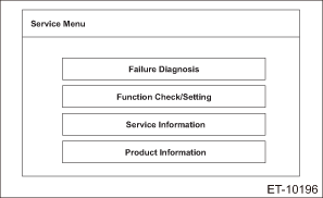
Upon entering the service diagnostics mode, the following screen is displayed.
Failure Diagnosis menu
On Service Menu, click Failure Diagnosis to display the following screen.
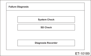
NOTE:
SD Check is displayed only for the navigation system.
1. System Check
On the Failure Diagnosis screen, click System Check to display the following screen.
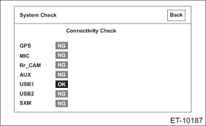
OK: Each connection device is connected properly.
NG: Connection is not established, or connection status (including harness) is faulty.
Check the connection status of the connector and harness. If there are no problems, the connection device or unit could be faulty.
NOTE:
• Check the external connection terminals (USB 1, USB 2 and AUX) by connecting memory or a pin jack for inspection.
• The following shows information to be displayed and its description.
Item | Item detection method | OK judgment condition | Note |
GPS | Direct line | GPS antenna is connected. (NG is displayed when short circuit is detected.) | Only model with navigation system |
MIC | Direct line | (i87) No. 6 falls to GND level. | — |
Rr_CAM | Direct line | Synchronized signals from the camera are input to (i146) No. 3. | — |
AUX | Direct line | (i87) No. 25 falls to GND level. | — |
USB1 | Communication | USB device is connected to USB-HUB to obtain USB device information properly. (Should be recognizable as a supported USB device.) | — |
USB2 | Communication | USB device is connected to USB-HUB to obtain USB device information properly. (Should be recognizable as a supported USB device.) | — |
SXM | Direct line | XM-ANT is connected. (NG is displayed when short circuit is detected.) | It takes approx. 30 seconds to become recognizable. |
2. SD Check
On the Failure Diagnosis screen, click SD Check to display the following screen.
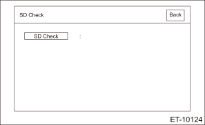
On the SD Check screen, click SD Check to display a diagnostic result.
OK: There is no defect on the SD card.
NG: There is defect on the SD card.
NOTE:
The following shows information to be displayed and its description.
Item | Content |
OK | SD card diagnosis is completed. Diagnostic result is OK. |
NG | SD card diagnosis is completed. Diagnostic result is NG. |
During diagnosis | SD card diagnosis is in progress. |
Function Check/Setting
On Service Menu, click Function Check/Setting to display the following screen.
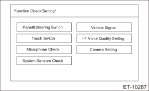
NOTE:
System Sensors Check is displayed only for the navigation system.
1. Panel & Steering Switch Check Mode
On the Function Check/Setting screen, click Panel & Steering Switch to display the following screen.
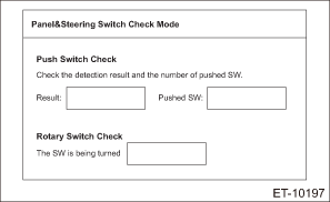
Once the screen is displayed, press the push switches to check that the number of pushed switches matches the number shown in Pushed SW.
If the number of SW does not match, SW conditions are not properly recognized. Therefore, perform inspection for unrecognized switches.
In addition, turn the rotary switch clockwise or counterclockwise to check that the screen indicates correct status according to the operation. If the screen display does not match the actual operation, the rotary SW may be faulty. Perform inspection for the rotary SW.
NOTE:
The following shows information to be displayed and its description.
Item | Display | Content |
Result | Pressed | Pressing of switch is detected. |
Number of switch pushed | 1 | One pressed switch is detected. |
2 | Two pressed switches are detected. | |
3 | Three pressed switches are detected. | |
4 | Four pressed switches are detected. | |
Direction of switch rotation | Clockwise | The rotary switch is turned clockwise. |
Counterclockwise | The rotary switch is turned counterclockwise. |
2. Touch Switch Check
On the Function Check/Setting screen, click Touch Switch to display the following screen.
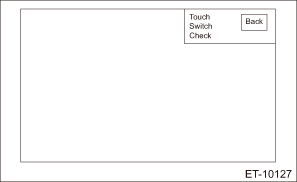
Once the screen appears, touch the screen. + (cursor) appears where you touched.
NOTE:
The following shows information to be displayed and its description.
Item | Content |
+ (Cursor) | Appears when the screen is touched. The displayed white-outlined + (cursor) stays on, even when a touching finger is removed, until the screen is switched. |
3. Microphone Check
On the Function Check/Setting screen, click Microphone Check to perform inspection for microphone.
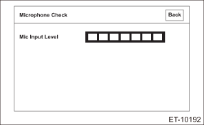
With the microphone input level screen displayed, make sound toward the microphone.
Fluctuate the sound volume to check that the microphone input level changes accordingly.
If the input level does not become green or the input level does not change even when the sound volume is fluctuated, the microphone may be faulty.
4. System Sensors Check
On the Function Check/Setting screen, click Touch Switch to display the following screen.
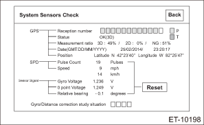
GPS related check: Status of the GPS signal reception can be checked. When there is faulty in reception status, position detection or date indication, re-check the reception status at a location with a fine view and no obstacles around that will interrupt the signal reception. When normal condition is still not obtained, the GPS antenna may be faulty.
• GPS/Reception number: Normal when it is indicated in blue.
• GPS/Status: Normal when OK is indicated.
• GPS/Measurement ratio 3D:
• GPS/Measurement ratio 2D:
• GPS/Date: Normal when current time is indicated. When current date/time is not indicated, click the Date Setting button to set the current date on the displayed date setting screen.
• GPS/Position: Normal when longitude and latitude of the current position are indicated.
SPD check: Status of the vehicle speed sensor signal can be checked.
(1) Before starting inspections, check the safety around the vehicle. (Lift up the vehicle as necessary.)
(2) When VDC CM detected DTC, clear the DTC.
(3) Drive the vehicle at 9 km/h (6 MPH) or more.
(4) Check that SPD indicates vehicle speed that is almost equivalent to the figure displayed on the combination meter.
(5) Vehicle speed is not displayed. Or, when the vehicle speed is not correct, check if the DTC related to the vehicle sensor is stored for the VDC system, and perform inspection according to the procedure. If no fault is found with the vehicle speed sensor, and the vehicle speed is displayed on the combination meter, the unit itself may be faulty.
Gyro sensor related check: Status of the Gyro sensor signal can be checked. If fault is found with the Gyro sensor related indications, the main unit could be faulty.
• Gyro sensor/Gyro Voltage: Shake the vehicle to the left and right to check that the voltage changes.
• Gyro sensor/Relative bearing: Normal when the value changes when direction of the vehicle is changed.
• Inclined angle sensor/relative angle: Park the vehicle on uphill or downhill surface. Normal when the value changes.
• Gyro/Distance correction study situation: Study situation can be checked.
• Reset: Press and hold the Reset button for three seconds to reset the pulse count of SPD, relative bearing of Gyro sensor, relative angle of inclined angle sensor.
NOTE:
The following shows information to be displayed and its description.
Item | Display | Content |
GPS/Reception number | Blue | When notification of “Positioning with collected data is used” is received from the GPS reception device. (Status: In-use) |
Yellow | When notification of “Tracking in progress” is received from the GPS reception device. (Status: Reception in progress) | |
Transparent | When notification of “Positioning with collected data is not used” or “Searching in progress” is received from the GPS reception device. (Status: Not used) | |
GPS/Status | OK (H3D) | When three-dimensional positioning (Hyper 3D positioning) using satellites with less accuracy degradation is used. |
OK (H2D) | When two-dimensional positioning (Hyper 2D positioning) using satellites with less accuracy degradation is used. | |
OK (3D) | When three-dimensional positioning is used. | |
OK (2D) | When two-dimensional positioning is used. | |
NG | When the positioning data is not available. | |
error | When a reception error occurred. | |
— | For cases other than above. | |
GPS/Measurement ratio 3D | Ratio | Displays ratio of three-dimensional positioning satellites. |
GPS/Measurement ratio 2D | Ratio | Displays ratio of two-dimensional positioning satellites. |
GPS/Measurement ratio NG | Ratio | Displays ratio of non-positioning satellites. |
GPS/Date | Current date and time | Displays date information obtained from GPS in four digits for year and 24-hour clock for time. Date information is displayed as [Y/M/D]. |
GPS/Position (latitude) | Current position, latitude information | Displays latitude information of the current position in “degree”, “minute” and “second”. When positioning information is not obtained, it appears as 00° 00’ 00”. |
GPS/Position (longitude) | Current position, longitude information | Displays longitude information of the current position in “degree”, “minute” and “second”. When positioning information is not obtained, it appears as 00° 00’ 00”. |
SPD/Pulse Count | Pulse count | Displays SPD signal status in the following format. |
• The number of input pulses accumulated since this screen is displayed. (Indicated in four-digit DEC code.)
• The number returns to 0 after 9999.
• Reset with ACC OFF/ON.
SPD/Speed
Speed
Displays SPD signal status in the following format.
• LSB: Displays in km-per-hour as 1 [km/h].
• Displays 255 [km/h] for MAX value or more, and 0 [km/h] for MIN value or less.
Gyro sensor/Gyro Voltage
Voltage value
Voltage value (unit: V, LSB: 1mV)
Gyro sensor/0 point Voltage
Unit: 0 point voltage
Displays 0 point voltage of the Gyro sensor used by each company.
Gyro sensor/Relative bearing
Relative bearing
−360.0° — +360.0°
Inclined angle sensor/relative angle
Relative angle
Displays longitudinal inclination angle of the vehicle in the relative angle (unit: °, LSB: 1°, no sign for elevation angle, negative sign for depression angle: −), while the position when this screen appears is set as [0°].
Gyro/Distance correction study situation
Gyro/Distance correction study situation
Gyro/Distance correction study situation is displayed.
Reset
Reset the following display items to [0].
• SPD pulse count
• Relative bearing of Gyro sensor
• Relative angle of inclined angle sensor
Press and hold the reset button for three seconds or more.
5. Vehicle Signal Check
On the Function Check/Setting screen, click Vehicle Signal to display the following screen.
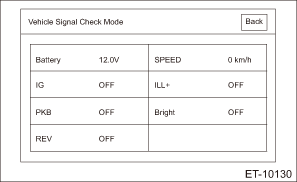
• Battery: Status of the battery voltage signal input can be checked.
Measure the battery voltage using a tester. System is normal when the indicated voltage is almost equivalent to the tester value. When the indicated voltage is different from the tester value, perform inspection for the power supply circuit of main unit.
• SPEED: Status of the vehicle speed signal input can be checked.
1. Before starting inspections, check the safety around the vehicle. (Lift up the vehicle as necessary.)
2. When VDC CM detected DTC, clear the DTC.
3. Drive the vehicle at 9 km/h (6 MPH) or more.
4. Check that SPD indicates vehicle speed that is almost equivalent to the figure displayed on the combination meter.
5. Vehicle speed is not displayed. Or, when the vehicle speed is not correct, check if the DTC related to the vehicle sensor is stored for the VDC system, and perform inspection according to the procedure. If no fault is found with the vehicle speed sensor, and the vehicle speed is displayed on the combination meter, the unit itself may be faulty.
• IG: Status of the IG signal input can be checked.
Turn the ignition switch to ON, and check that the IG indication appears as ON. If the indication does not appear as ON, check the IG signal line.
• ILL+: Status of the illumination signal input can be checked.
1. Before starting inspections, turn the ignition to ON.
2. Set the lighting switch to the parking position.
Make sure that the bright switch is not turned ON at this time.
3. Check that ON lights in ILL+ and then the screen becomes dim.
ON: Normal.
OFF: Abnormal. Check the signal line and connector. If no faulty is found, the unit itself may be faulty.
• PKB: Status of the parking brake signal input can be checked.
• GPS: Normal when longitude and latitude of the current position are indicated.
Pull parking brake lever. Check that ON is displayed in PKB.
ON: Normal.
OFF: Abnormal. Check the signal line and connector. If no faulty is found, the unit itself may be faulty.
• Bright: Status of the Bright signal input can be checked.
Operate the dial-type bright switch next to the steering wheel. System is normal when the signal indicates ON.
If the signal does not indicate ON, check the bright switch.
• REV: Status of the reverse range signal input can be checked.
1. Before starting inspections, check the safety around the rear end of the vehicle and then turn the ignition to ON.
2. Pull the parking brake lever and depress the brake pedal, then place the select lever or gear shift lever in reverse.
3. Check that ON is displayed in REV.
ON: Normal.
OFF: Abnormal. Check the signal line and connector. If no faulty is found, the unit itself may be faulty.
NOTE:
The following shows information to be displayed and its description.
Item | Display | Content |
Battery | Status of battery voltage | 0 [V] — 24.0 [V] (Minimum unit: 0.1 [V]) |
SPEED | Status of vehicle speed | 0 [km/h] — 255 [km/h] (Minimum unit 1 [km/h]) |
IG | ON | IG power supply ON |
OFF | IG power supply OFF | |
ILL+ | ON | ILL+ signal ON |
OFF | ILL+ signal OFF | |
PKB | ON | PKB signal ON |
OFF | PKB signal OFF | |
Bright | ON | Bright with dimmer |
OFF | Bright without dimmer | |
REV | ON | REV signal ON |
OFF | REV signal OFF |
6. Hands-free voice quality setting
On the Function Check/Setting screen, click Hands-Free Voice Quality Setting to display the following screen.
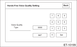
Setting of the hands-free voice quality setting is possible.
7. Camera setting
On the Function Check/Setting screen, click Camera Setting to display the following screen.
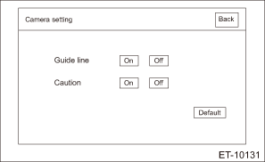
Setting of the rearview camera adjustment is possible.
• Guide line: Turn ON the guide line display to show the guide lines.
• Caution: Turn ON the caution display to enable caution display during the rearview camera display.
• Default: Click the Default button to return the Guide line display and Caution display settings to the initial settings.
NOTE:
The following shows information to be displayed and its description.
Item | Content |
Guide line | Guide line display setting switch |
• Turns on/off the guide line display for the rearview camera display screen.
• When On is selected, guide lines will appear on the rearview camera display screen.
Caution
Caution display setting switch
• Turns on/off the caution display for the rearview camera display screen.
• When On is selected, the caution will appear on the rearview camera display screen.
Default
Default setting switch
• Returns the Guide line display setting and Caution display setting to the default settings.
Service Information
On Service Menu, click Service Information to display the following screen.
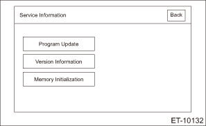
• Program Update: This function is used when the main unit program is updated, and not used as troubleshooting.
• Version Information: This function is used to view version of the main unit, and not used as troubleshooting.
• Memory Initialization: This function is used to initialize information stored in the main unit memory.
CAUTION:
When this function is used, music information and navigation setting information saved in the main unit will be deleted. Therefore, obtain permission from the user before using this function.
When initializing the memory, perform procedures by following the indicated messages. Also, when clicking the OK button, press and hold it.
Product information
On Service Menu, click Product Information to display the following screen.
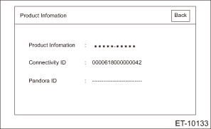
• Product Information: Displays the product number of the main unit.
• Connectivity ID: ID that is required upon using the SUBARU STARLINK functions. When this ID is not indicated, the SUBARU STARLINK functions are not accessible.
• Pandora ID: ID that is required upon using Pandora. When this ID is not indicated, Pandora is not accessible.
 Navigation body Note
ENTERTAINMENT > Navigation BodyNOTEFor the operation procedures for navigation assembly, refer to “Audio” section. Audio"> ...
 Exhaust(h4do)
...
Other materials:
Dtc u0427 invalid data received from vehicle security control module
LAN SYSTEM (DIAGNOSTICS) > Diagnostic Procedure with Diagnostic Trouble Code (DTC)DTC U0427 INVALID DATA RECEIVED FROM VEHICLE SECURITY CONTROL MODULEDTC DETECTING CONDITION:Defective data was transmitted from keyless access CM.TROUBLE SYMPTOM:Cooperation control of keyless access does not operat ...
Removal
SECURITY AND LOCKS > Accessory Relay (Push Button Start)REMOVALCAUTION:Before handling the airbag system components, refer to “CAUTION” of “General Description” in “AIRBAG SYSTEM”. General Description > CAUTION">1. Disconnect the ground cable from b ...
Triple meter setting
1. Perform the preparation steps according
to "Preparation for screen settings"
2. Operate the "
" or "
" switch to
select the "Triple Meter" item. Then push
the
button.
3. Select the setting location (left, center
or right) by operating the "
" or "
"
...
