Subaru Crosstrek Service Manual: Removal
POWER ASSISTED SYSTEM (POWER STEERING) > Steering Column
REMOVAL
CAUTION:
Before handling the airbag system components, always refer to “CAUTION” of “General Description” in “AIRBAG SYSTEM”. General Description > CAUTION">
1. Disconnect the ground cable from battery and wait for at least 60 seconds before starting work. NOTE">
2. Remove the driver’s airbag module. Driver’s Airbag Module > REMOVAL">
3. Remove the steering wheel. Steering Wheel > REMOVAL">
4. Remove the cover assembly - instrument panel LWR driver. Instrument Panel Lower Cover > REMOVAL">
5. Remove the knee airbag module. Knee Airbag Module > REMOVAL">
6. Remove the cover assembly - column.
(1) Release the screws and claws.
(2) Remove the cap - key cylinder (a). (Model with keyless access with push button start)
(3) Remove the cover assembly - column UPR and the cover assembly - column LWR.
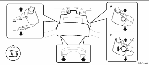
A | Model without keyless access with push button start | B | Model with keyless access with push button start |
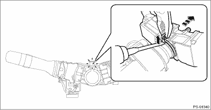
7. Remove the switch assembly - combination.
(1) Disconnect the connector, and loosen the clamp to release the claws.
(2) Pull out the switch assembly - combination from the column assembly - steering.
8. Remove all connectors from the column assembly - steering.
9. Remove the universal joint assembly - steering. Universal Joint > REMOVAL">
CAUTION:
To prevent damage to the universal joint assembly - steering and improper steering effort, make sure to remove the universal joint assembly - steering.
10. Remove the two nuts under the beam COMPL - steering securing the column assembly - steering.
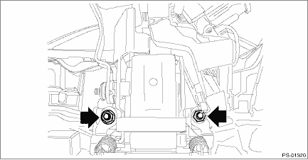
11. Pull out the column assembly - steering from the hole on toe board.
CAUTION:
Do not loosen the tilt lever when the column assembly - steering is not secured to the vehicle.
12. Remove the ignition key lock from the column assembly - steering. Ignition Key Lock > REPLACEMENT">
 Inspection
POWER ASSISTED SYSTEM (POWER STEERING) > Steering ColumnINSPECTION1. UNIT INSPECTIONCheck the following items, and if there is anything out of standard value, it is considered to be damaged. If so, ...
 Installation
POWER ASSISTED SYSTEM (POWER STEERING) > Steering ColumnINSTALLATIONCAUTION:If the steering wheel and steering angle sensor are removed, perform the following VDC setting mode.– Model without Ey ...
Other materials:
Malfunction indicator light remains blinking
ENGINE (DIAGNOSTICS)(H4DO) > Malfunction Indicator LightMALFUNCTION INDICATOR LIGHT REMAINS BLINKINGDiagnosis:The delivery (test) mode fuse circuit is short-circuited to ground.Trouble symptom:Malfunction indicator light blinks when delivery (test) mode fuse is not connected.Wiring diagram:Engine ...
Disassembly
CONTINUOUSLY VARIABLE TRANSMISSION(TR580) > Transfer ClutchDISASSEMBLY1. Remove the snap ring, and then remove the pressure plate, drive plate and driven plate.(A)Snap ring2. Compress the return spring using the ST to remove the snap ring.ST 18762AA001COMPRESSOR SPECIAL TOOL(A)Snap ring(B)Tran ...
Adjustment
LIGHTING SYSTEM > Headlight AssemblyADJUSTMENT1. HEADLIGHT BEAM ADJUSTMENTCAUTION:• Turn off the light before adjusting the beam level of the light assembly - head. If it is necessary to inspect the beam level, do not keep the light on for two minutes or more.• When blocking the light ...
