Subaru Crosstrek Service Manual: Removal
MECHANICAL(H4DO) > Cam Carrier
REMOVAL
1. CAM CARRIER RH
1. Remove the engine from the vehicle. Engine Assembly > REMOVAL">
2. Remove the chain cover. Chain Cover > REMOVAL">
3. Remove the timing chain RH. Timing Chain Assembly > REMOVAL">
4. Remove the cam sprocket RH. Cam Sprocket > REMOVAL">
NOTE:
This operation is required only when disassembling the cam carrier RH.
5. Remove the rocker cover RH. Rocker Cover > REMOVAL">
6. Remove the clip holding the engine harness from cam carrier RH.
7. Remove the water pipe assembly RH. Water Pipe Assembly > REMOVAL">
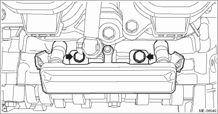
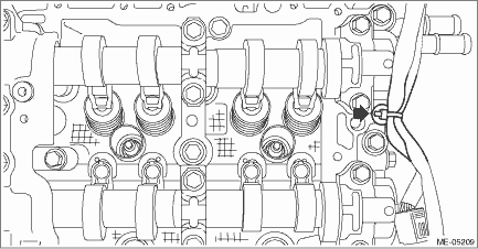
8. Remove the fuel pipe RH and the fuel injector RH.
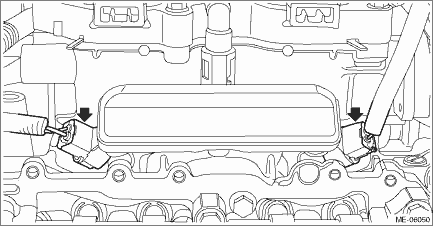
(1) Disconnect the connector from fuel injector RH.
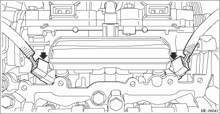
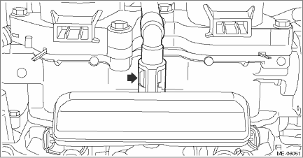
(2) Disconnect the quick connector from fuel pipe RH.
NOTE:
Disconnect the quick connector as shown in the figure.
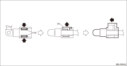
(a) | Slider |
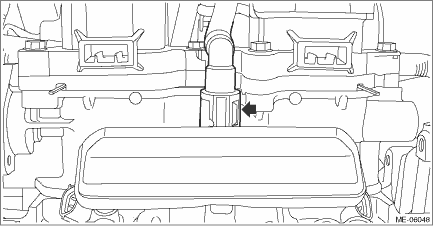
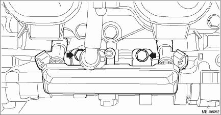
(3) Remove the bolts securing the fuel pipe RH, and remove the fuel pipe RH and the fuel injector RH.
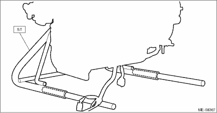
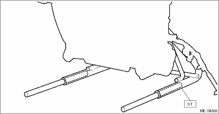
9. Insert the steel rods into ST, and set the engine so that the camshaft RH is facing up.
CAUTION:
• If the engine is standing on one side without inserting the steel rod into ST, engine may lose balance and fall down. Be sure to insert the steel rod into ST to extend the length.
• Use the steel rod with enough strength.
• Be careful not to pinch the engine harness with ST.
| ST 499817100 | ENGINE STAND |
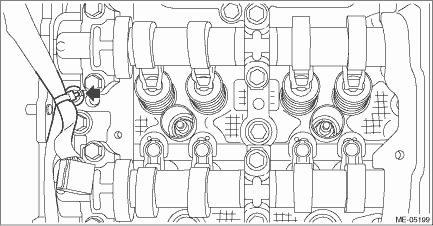
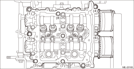
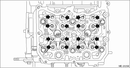
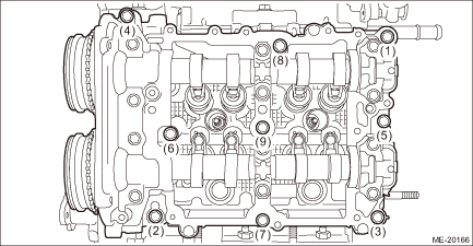
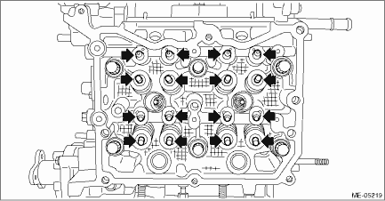
10. Loosen the bolts holding the cam carrier RH equally, a little at a time in numerical sequence as shown in the figure and remove the cam carrier RH.
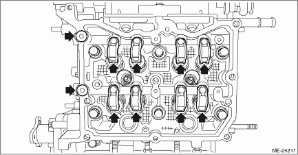
11. Remove the O-ring and the roller rocker arm from cylinder head RH.
NOTE:
Be careful not to confuse the roller rocker arms.
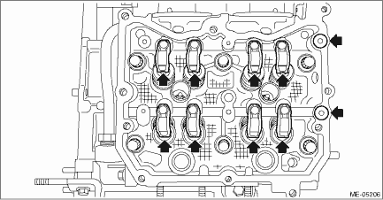
12. Remove the valve shim and the roller rocker arm pivot from cylinder head RH.
NOTE:
Be careful not to confuse the valve shim and the roller rocker arm pivot.
13. Remove the liquid gasket from cam carrier RH and cylinder head RH.
2. CAM CARRIER LH
1. Remove the engine from the vehicle. Engine Assembly > REMOVAL">
2. Remove the chain cover. Chain Cover > REMOVAL">
3. Remove the timing chain LH. Timing Chain Assembly > REMOVAL">
4. Remove the cam sprocket LH. Cam Sprocket > REMOVAL">
NOTE:
This operation is required only when disassembling the cam carrier LH.
5. Remove the rocker cover LH. Rocker Cover > REMOVAL">
6. Remove the clip holding the engine harness from cam carrier LH.
7. Remove the water pipe assembly LH. Water Pipe Assembly > REMOVAL">
8. Remove the fuel pipe LH and the fuel injector LH.
(1) Disconnect the connector from fuel injector LH.
(2) Disconnect the quick connector from fuel pipe LH.
NOTE:
Disconnect the quick connector as shown in the figure.
(a) | Slider |
(3) Remove the bolts securing the fuel pipe LH, and remove the fuel pipe LH and the fuel injector LH.
9. Insert the steel rods into ST, and set the engine so that the camshaft LH is facing up.
CAUTION:
• If the engine is standing on one side without inserting the steel rod into ST, engine may lose balance and fall down. Be sure to insert the steel rod into ST to extend the length.
• Use the steel rod with enough strength.
• Be careful not to pinch the engine harness with ST.
| ST 499817100 | ENGINE STAND |
10. Loosen the bolts holding the cam carrier LH equally, a little at a time in numerical sequence as shown in the figure and remove the cam carrier LH.
11. Remove the O-ring and the roller rocker arm from cylinder head LH.
NOTE:
Be careful not to confuse the roller rocker arms.
12. Remove the valve shim and the roller rocker arm pivot from cylinder head LH.
NOTE:
Be careful not to confuse the valve shim and the roller rocker arm pivot.
13. Remove the liquid gasket from cam carrier LH and cylinder head LH.
 Assembly
MECHANICAL(H4DO) > Cam CarrierASSEMBLY1. CAM CARRIER RH1. Install the filter to the cam carrier RH.NOTE:Use a new filter.Filter insert position:Cam carrier RH end face 0+0 −0.5 mm (+0 − ...
 Disassembly
MECHANICAL(H4DO) > Cam CarrierDISASSEMBLY1. CAM CARRIER RH1. Loosen the bolts (front camshaft cap RH, intake center camshaft cap RH, intake rear camshaft cap RH, exhaust center camshaft cap RH, and ...
Other materials:
Dtc b27a7 trunk/rear gate internal antenna open
KEYLESS ACCESS WITH PUSH BUTTON START SYSTEM (DIAGNOSTICS) > Diagnostic Procedure with Diagnostic Trouble Code (DTC)DTC B27A7 TRUNK/REAR GATE INTERNAL ANTENNA OPENDTC detecting condition:When open circuit occurs in the harness between keyless access CM and rear interior antenna.Trouble symptom:Ke ...
Removal
POWER ASSISTED SYSTEM (POWER STEERING) > Universal JointREMOVAL1. Adjust the tilt position of the column assembly - steering to the lowest position and lock the tilt lever.2. Remove the universal joint assembly - steering.(1) Place alignment marks on the universal joint assembly - steering.NOTE:P ...
Preparation tool
ENTERTAINMENT > General DescriptionPREPARATION TOOL1. SPECIAL TOOLILLUSTRATIONTOOL NUMBERDESCRIPTIONREMARKS — SUBARU SELECT MONITOR 4Used for setting of each function and troubleshooting for electrical system.NOTE:For detailed operation procedures of Subaru Select Monitor 4, refer to “App ...
