Subaru Crosstrek Service Manual: Removal
ENTERTAINMENT > Antenna
REMOVAL
1. RADIO/TELEMATICS ANTENNA
CAUTION:
Before handling the airbag system components, refer to “CAUTION” of “General Description” in “AIRBAG SYSTEM”. General Description > CAUTION">
1. Disconnect the ground cable from battery and wait for at least 60 seconds before starting work. NOTE">
2. Remove the trim panel - roof assembly. Roof Trim > REMOVAL">
3. Remove the antenna assembly - radio or telematics.
(1) Disconnect the connector and terminal, and remove the mounting nut (A).
(2) Pull out the antenna assembly - radio or telematics from the roof panel top.
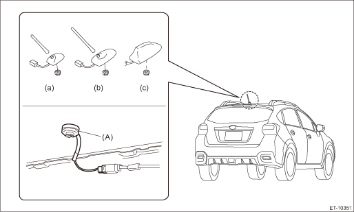
(a) | Radio antenna | (b) | XM radio antenna | (c) | Telematics antenna |
2. ANTENNA FEEDER CORD
CAUTION:
Before handling the airbag system components, refer to “CAUTION” of “General Description” in “AIRBAG SYSTEM”. General Description > CAUTION">
1. Disconnect the ground cable from battery and wait for at least 60 seconds before starting work. NOTE">
2. Remove the trim panel - roof assembly. Roof Trim > REMOVAL">
3. Remove the cover assembly - instrument panel LWR driver and the knee airbag module. Knee Airbag Module > REMOVAL">
4. Remove the glove box. Glove Box > REMOVAL">
5. Remove the center grille assembly. Air Vent Grille > REMOVAL">
6. Remove the audio assembly or navigation assembly. Audio > REMOVAL">
7. Turn over the floor mat. Floor Mat > REMOVAL">
8. Remove the cord assembly - antenna feeder.
3. TELEMATICS SUB ANTENNA
CAUTION:
Before handling the airbag system components, always refer to “CAUTION” of “General Description” in “AIRBAG SYSTEM”.
1. Disconnect the ground cable from battery and wait for at least 60 seconds before starting work. NOTE">
2. Remove the cover assembly - instrument panel LWR driver and the knee airbag module. Knee Airbag Module > REMOVAL">
3. Remove the glove box. Glove Box > REMOVAL">
4. Remove the center grille assembly. Air Vent Grille > REMOVAL">
5. Remove the audio assembly or navigation assembly. Audio > REMOVAL">
NOTE:
The data communication module will be removed at the same time.
6. Remove the combination meter assembly. Combination Meter > REMOVAL">
7. Remove the GPS antenna.
NOTE:
Remove the antenna only. Do not pull the cord.
8. Remove the telematics sub antenna.
(1) Disconnect the telematics sub antenna connector on the data communication module side, and tie a string to the connector.
NOTE:
A string makes operation easier during installation.
(2) Remove the screw and harness clamp, and pull out the telematics sub antenna from the combination meter side.
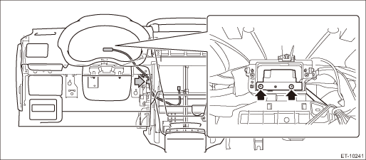
(3) After the telematics sub antenna has been pulled out, remove the string attached to the connector in step (1).
 Installation
ENTERTAINMENT > AntennaINSTALLATIONCAUTION:• After installing the center grille assembly, check that the air vent grille of the center grille assembly is inserted correctly into the air vent ...
 Audio
Audio
...
Other materials:
Cruise control system Wiring diagram
WIRING SYSTEM > Cruise Control SystemWIRING DIAGRAM ...
Shock sensors (dealer option)
The shock sensors trigger the alarm
system when they sense impacts applied
to the vehicle and when any of their
electric wires are cut. The alarm system
causes the horn to sound and the hazard
warning flashers to flash for a short time
when the sensed impact is weak, but it
warns of a strong ...
Dtc p0196 engine oil temperature sensor "a" range/performance
ENGINE (DIAGNOSTICS)(H4DO) > Diagnostic Procedure with Diagnostic Trouble Code (DTC)DTC P0196 ENGINE OIL TEMPERATURE SENSOR "A" RANGE/PERFORMANCEDTC DETECTING CONDITION:Detected when two consecutive driving cycles with fault occur.TROUBLE SYMPTOM:• Hard to start• Improper id ...
