Subaru Crosstrek Service Manual: Removal
DRIVE SHAFT SYSTEM > Front Hub Unit Bearing
REMOVAL
1. Lift up the vehicle, and then remove the front wheels.
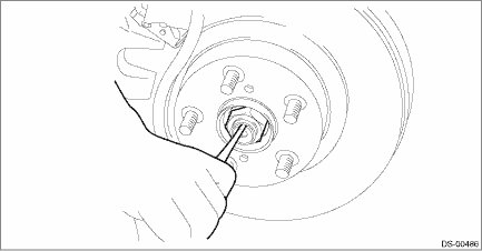
2. Remove the axle nut.
CAUTION:
Do not loosen the axle nut while the front axle is loaded. Doing so may damage the hub unit bearing.
(1) Lift the crimped section of axle nut.
(2) Remove the axle nut using a socket wrench while depressing the brake pedal.
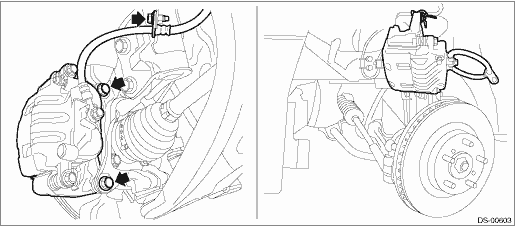
3. Remove the caliper body assembly from the front axle housing.
(1) Remove the mounting bolts and the brake hose bracket, and remove the caliper body assembly.
(2) Prepare wiring harnesses etc. to be discarded, and suspend the caliper body assembly from the strut assembly.
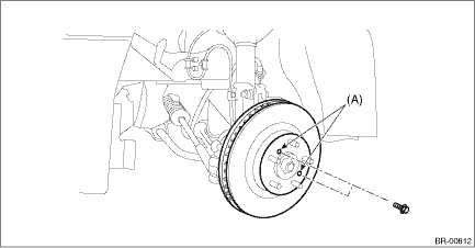
4. Remove the disc rotor.
NOTE:
When the disc rotor is difficult to be removed from the front hub unit bearing, screw in 8 mm (0.31 in) bolt to the threaded part of the disc rotor (A), and remove the disc rotor.
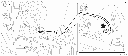
5. Remove the bolts, and remove the front ABS wheel speed sensor.
6. Remove the bolt from the front axle housing, and remove the front hub unit bearing.
CAUTION:
• Do not get closer the tool which charged magnetism to magnetic encoder.
• Be careful not to damage the magnetic encoder.
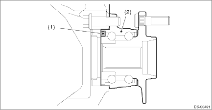
(1) | Magnetic encoder | (2) | Front hub unit bearing |
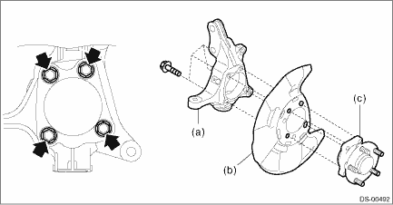
(a) | Front axle housing | (b) | Front brake back plate | (c) | Front hub unit bearing |
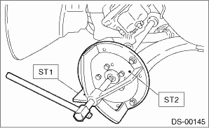
NOTE:
If it is hard to remove, use the ST.
Preparation tool:
ST1: AXLE SHAFT PULLER (926470000)
ST2: AXLE SHAFT PULLER PLATE (28099PA110)
 Assembly
DRIVE SHAFT SYSTEM > Front Hub Unit BearingASSEMBLY1. Install the hub unit bearing to the ST securely.Preparation tool:ST: HUB STAND (927080000)2. Using a press, press the new hub bolts (b) until t ...
 Disassembly
DRIVE SHAFT SYSTEM > Front Hub Unit BearingDISASSEMBLYUsing the ST or a hydraulic press, push out the hub bolt (b) from the front hub unit bearing (a).CAUTION:• Be careful not to hammer the h ...
Other materials:
Dtc c0073 lateral g sensor power/output
VEHICLE DYNAMICS CONTROL (VDC) (DIAGNOSTICS) > Diagnostic Procedure with Diagnostic Trouble Code (DTC)DTC C0073 LATERAL G SENSOR POWER/OUTPUTNOTE:For the diagnostic procedure, refer to “DTC C0073 ABNORMAL LATERAL G SENSOR OUTPUT”. Diagnostic Procedure with Diagnostic Trouble Code (DT ...
Electrical specification
HVAC SYSTEM (AUTO A/C) (DIAGNOSTICS) > Auto A/C Control Module I/O SignalELECTRICAL SPECIFICATIONTerminal No.ContentMeasuring conditionStandard1Mode door actuator #4Digital signal; can not be measured — 2Mode door actuator #3Digital signal; can not be measured — 3Mode door actuator #2Digital ...
Dtc u0122 lost communication with vehicle dynamics control module
CONTINUOUSLY VARIABLE TRANSMISSION (DIAGNOSTICS) > Diagnostic Procedure with Diagnostic Trouble Code (DTC)DTC U0122 LOST COMMUNICATION WITH VEHICLE DYNAMICS CONTROL MODULENOTE:Refer to “LAN SYSTEM (DIAGNOSTICS)” for diagnostic procedures. Basic Diagnostic Procedure">1. OUTLIN ...
