Subaru Crosstrek Service Manual: Removal
CONTROL SYSTEMS > Select Lever
REMOVAL
1. Shift the select lever to “N” range.
2. Disconnect the ground cable from battery. NOTE">
NOTE:
For model with battery sensor, disconnect the ground terminal from battery sensor.
3. Lift up the vehicle.
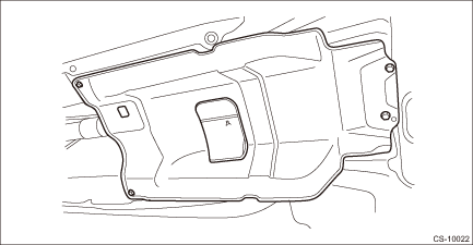
4. Remove the center exhaust pipe. Center Exhaust Pipe > REMOVAL">
5. Remove the center exhaust cover.
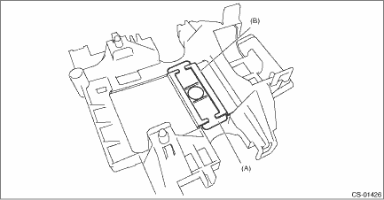
6. Disconnect the cable from the arm COMPL.
CAUTION:
Do not apply extra overload while holding the part (A).
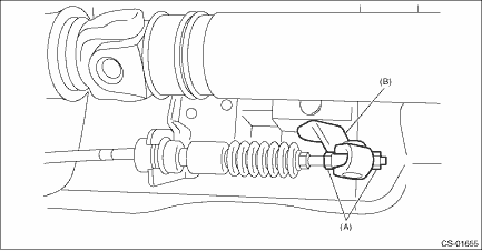
(A) | Adjusting nut |
(B) | Arm COMPL |
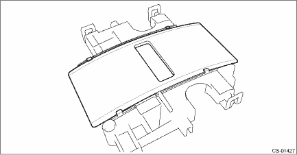
7. Raise the claw of clamp and remove the cable.
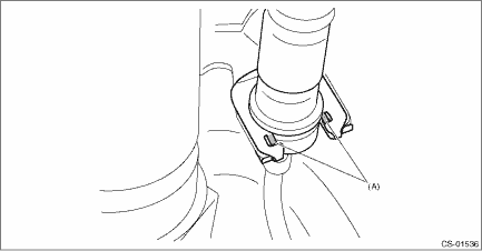
(A) | Claw |
8. Lower the vehicle.
9. Shift the select lever to “N” range.
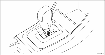
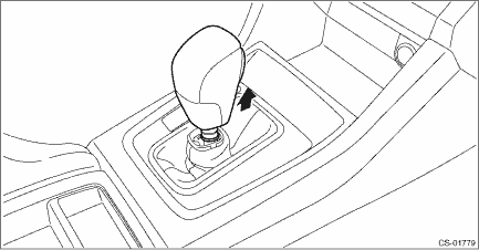
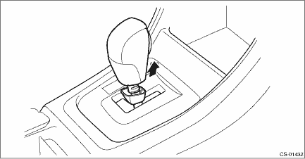
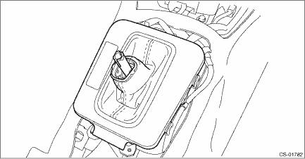
10. Lower the boot assembly vertically toward the lever. (Model with boot shifter)
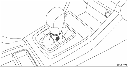
11. Lower the cover grip AT vertically toward the lever. (Model with gate shifter)
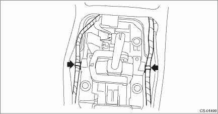
12. Remove the clamp grip pin.
• Model with boot shifter
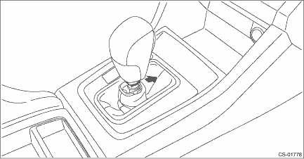
• Model with gate shifter
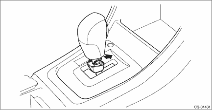
13. Remove the grip assembly.
• Model with boot shifter
• Model with gate shifter
14. Remove the console box. Console Box > REMOVAL">
15. Remove the cover - shift lever. Console Box > REMOVAL">
16. Disconnect the connector, and remove the indicator cover from the housing. (Model with gate shifter)
17. Remove the housing with the blind A and blind B. (Model with gate shifter)
18. Remove the blind B. (Model with gate shifter)
(A) | Blind B |
(B) | Blind A |
19. Remove the blind A from the housing. (Model with gate shifter)
20. Remove the panel center LWR LH and RH. Console Box > REMOVAL">
21. Disconnect the connector, and remove the indicator assembly. (Model with boot shifter)
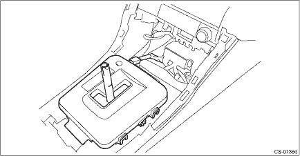
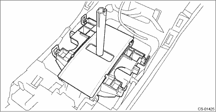
22. Remove the harness clip from the select lever assembly.
23. Disconnect the harness connector.
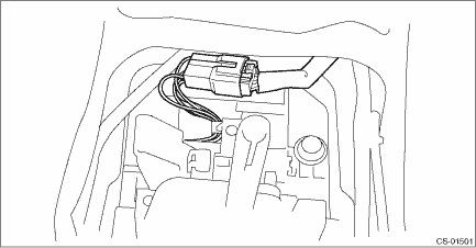
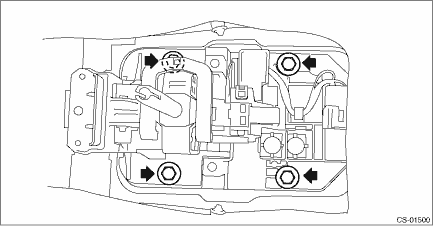
24. Remove the four bolts to remove the select lever assembly.
 Assembly
CONTROL SYSTEMS > Select LeverASSEMBLY1. Clean all the parts before assembly.2. Apply Multemp D or equivalent to the sliding portion of each part.3. Assemble in the reverse order of disassembly.NOT ...
 Disassembly
CONTROL SYSTEMS > Select LeverDISASSEMBLY1. GRIP ASSY1. Remove the button assembly_AT.(A)Claw2. Remove the rod COMPL.2. AT SELECT LEVER ASSEMBLY1. Remove the spacer plate.2. Remove the gasket.3. In ...
Other materials:
Dtc b1801 open in driver s airbag
AIRBAG SYSTEM (DIAGNOSTICS) > Diagnostic Chart with Trouble CodeDTC B1801 OPEN IN DRIVER’S AIRBAGDiagnosis start condition:Ignition voltage is 10 V to 16 V.DTC detecting condition:• Airbag main harness circuit is open.• Airbag module harness (driver’s side) circuit is open ...
Dtc p1532 battery charging system
ENGINE (DIAGNOSTICS)(H4DO) > Diagnostic Procedure with Diagnostic Trouble Code (DTC)DTC P1532 BATTERY CHARGING SYSTEMDTC detecting condition:Immediately at fault recognitionCAUTION:After servicing or replacing faulty parts, perform Clear Memory Mode Clear Memory Mode > OPERATION">, an ...
List
KEYLESS ACCESS WITH PUSH BUTTON START SYSTEM (DIAGNOSTICS) > Read Current DataLIST(1) Keyless access systemItems to be displayedUnit of measureContentNoteDriver’s unlock touch sensor switchON/OFFKeyless access CM input valueON when the touch sensor (unlock) built on the back surface of the ...
