Subaru Crosstrek Service Manual: Preparation tool
MECHANICAL(H4DO) > General Description
PREPARATION TOOL
1. SPECIAL TOOL
ILLUSTRATION | TOOL NUMBER | DESCRIPTION | REMARKS |
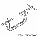
0920287002000
REMOVER AND REPLACER
Used for removing and installing valve spring.
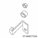
498277200
STOPPER SET
Used for preventing the torque converter from falling when removing and installing the engine. (CVT model)
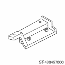
498457000
ENGINE STAND ADAPTER RH
• Used for disassembling and assembling engine.
• Used together with ENGINE STAND (499817100) and ADAPTER (18362AA020).
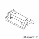
498457100
ENGINE STAND ADAPTER LH
• Used for disassembling and assembling engine.
• Used together with ENGINE STAND (499817100) and ADAPTER (18362AA020).
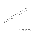
499765700
VALVE GUIDE REMOVER AND INSTALLER
Used for removing and installing valve guide.
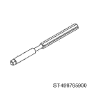
499765900
VALVE GUIDE REAMER
Used for reaming valve guides.
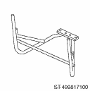
499817100
ENGINE STAND
• Used for disassembling and assembling engine.
• Used together with ADAPTER (18362AA020), ENGINE STAND ADAPTER RH (498457000) and LH (498457100).
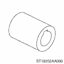
18252AA000
CRANKSHAFT SOCKET
Used for rotating crankshaft.
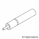
18261AA010
VALVE OIL SEAL GUIDE
Used for press-fitting of intake valve guide stem seals and exhaust valve guide stem seals.
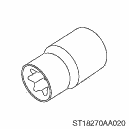
18270AA020
SOCKET
Used for removing and installing connecting rod.
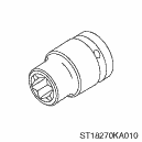
18270KA010
SOCKET
Used for installing and removing cam sprocket.

18334AA000
PULLEY WRENCH PIN SET
• Used for removing and installing the crank pulley.
• Used together with PULLEY WRENCH (18355AA000).
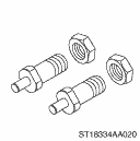
18334AA020
PULLEY WRENCH PIN SET
• Used for rotating the intake cam sprocket LH.
• Used for removing and installing cam sprocket.
• Used together with PULLEY WRENCH (18355AA000).
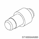
18350AA000
CONNECTING ROD BUSHING REMOVER AND INSTALLER
Used for removing and installing the connecting rod bushing at connecting rod small end.

18355AA000
PULLEY WRENCH
• Used for removing and installing the crank pulley.
• Used for rotating the intake cam sprocket LH.
• Used for removing and installing cam sprocket.
• Used together with PULLEY WRENCH PIN SET (18334AA000) or PULLEY WRENCH PIN SET (18334AA020).
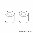
18362AA020
ADAPTER
• Used for disassembling and assembling engine.
• Used together with STAND (499817100), ENGINE STAND ADAPTER RH (498457000) and LH (498457100).
• Bolt used: M10 ? 50 (SUBARU genuine Part No.: 010410500)
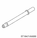
18471AA000
FUEL PIPE ADAPTER
Used for inspecting the fuel pressure.
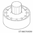
18657AA030
OIL SEAL INSTALLER
• Used for installing the rear oil seal of engine.
• Used together with OIL SEAL GUIDE (18671AA020).
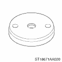
18671AA020
OIL SEAL GUIDE
• Used for installing the rear oil seal of engine.
• Used together with OIL SEAL INSTALLER (18657AA030).
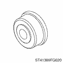
41399FG020
SPECIAL TOOL B
Used for installing the front oil seal of engine.
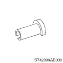
42099AE000
QUICK CONNECTOR RELEASE
Used for removing FUEL HOSE (42075AG690).
NOTE:
FUEL HOSE (42075AG690) is used for checking the fuel pressure.
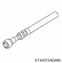
42075AG690
FUEL HOSE
Used for inspecting the fuel pressure.
NOTE:
This is the SUBARU genuine part.

—
SUBARU SELECT MONITOR 4
Used for setting of each function and troubleshooting for electrical system.
NOTE:
For detailed operation procedures of Subaru Select Monitor 4, refer to “Application help”.
2. GENERAL TOOL
TOOL NAME | REMARKS |
Compression gauge | Used for measuring compression. |
Vacuum gauge | Used for measuring intake manifold vacuum. |
Oil pressure gauge | Used for measuring engine oil pressure. |
Fuel pressure gauge | Used for measuring fuel pressure. |
Thickness gauge | Used for various inspections. |
Angle gauge | Used for angle tightening. |
Piston ring compressor | Used for installing the piston into the cylinder block. |
DST-i | Used together with Subaru Select Monitor 4. |
 Component
MECHANICAL(H4DO) > General DescriptionCOMPONENT1. TIMING CHAIN(1)Intake camshaft RH(8)Chain tensioner RH(15)Exhaust camshaft LH(2)Exhaust camshaft RH(9)Crank sprocket (3)Intake cam sprocket RH(10) ...
 Rocker cover
...
Other materials:
Rear seatbelts (except rear center seatbelt)
1. Sit well back in the seat.
2. Pick up the tongue plate and pull the
belt out slowly. Do not let it get twisted.
If the belt stops before reaching the
buckle, return the belt slightly and pull
it out more slowly.
If the belt still cannot be unlocked,
let the belt retract slightly a ...
Inspection
INSTRUMENTATION/DRIVER INFO (DIAGNOSTICS) > Subaru Select MonitorINSPECTION1. COMMUNICATION FOR INITIALIZING IMPOSSIBLE (COMBINATION METER)Detecting condition:• Defective harness connector• Power supply circuit malfunction• Defective combination meter• Defective CAN commun ...
Type B
1. Turn the airflow mode selection dial
and fan speed control dial to the "AUTO"
position.
2. Set the preferred temperature using
the temperature control dial.
NOTE
Each function can be individually
set to the AUTO mode independently of
the other functions. Any function set to
the A ...
