Subaru Crosstrek Service Manual: Precautions in trouble diagnosis and repair of electric parts
WIRING SYSTEM > Working Precautions
PRECAUTIONS IN TROUBLE DIAGNOSIS AND REPAIR OF ELECTRIC PARTS
1. The battery cable must be disconnected from the battery’s (−) terminal, and the ignition switch must be set to the OFF position, unless otherwise required by the diagnostics.
2. Securely fasten the wiring harness with clamps and clips so that the harness does not interfere with the body end parts, edges, bolts or screws.
3. When installing parts, be careful not to catch them on the wiring harness.
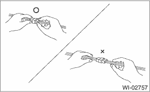
4. When disconnecting a connector, do not pull the wires, but pull while holding the connector body.
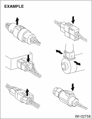
5. Some connectors are provided with a lock. One type of such a connector is disconnected by pushing the lock, and the other, by moving the lock up. In either type the lock shape must be identified before attempting to disconnect the connector.
To connect, insert the connector until it snaps and confirm that it is connected securely.
6. When checking continuity between connector terminals, or measuring voltage across the terminal and ground, always touch tester probe(s) to terminals from the wiring connection side. If the probe is too thick to gain access to the terminal, use “mini” test leads.
To check water-proof connectors (which are not measurable from the wiring side), touch test probes on the terminal side and be careful not to bend or damage the terminals.
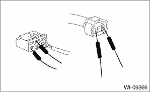
7. When measuring the voltage or resistance of individual sensor or all electrical control modules, use a tapered pin with a diameter of 0.6 mm (0.024 in) or less and touch it to the tip of terminal. Never insert the tapered pin into the terminal at this time. Doing so may cause internal deformation and a malfunction can occur.
8. Sensors, relays, electrical unit, etc., are sensitive to strong impacts.
Handle them with care so that they are not dropped or mishandled.
 Precautions when working with the parts mounted on the vehicle
WIRING SYSTEM > Working PrecautionsPRECAUTIONS WHEN WORKING WITH THE PARTS MOUNTED ON THE VEHICLE1. When working under a vehicle which is jacked-up, always be sure to use rigid rack.2. The parking ...
 Air conditioning system Wiring diagram
WIRING SYSTEM > Air Conditioning SystemWIRING DIAGRAM1. MANUAL A/C MODEL2. AUTO A/C MODEL ...
Other materials:
13
CRUISE CONTROL SYSTEM (DIAGNOSTICS) > Diagnostic Procedure with Cancel Code13Detected when clutch pedal is depressed or malfunction related to clutch switch occurs.TROUBLE SYMPTOM:• Cruise control cannot be set.• Cruise control cannot be released.WIRING DIAGRAM:Cruise control system ...
Rear Cross Traffic Alert (RCTA)
Operating range
The system notifies the driver of another
vehicle approaching from either side when
driving in reverse. This feature helps the
driver check the rear and side areas of the
vehicle when moving backward.
If the system detects a vehicle approaching
from either side whil ...
Glove box
Lock
Unlock
To open the glove box, pull the handle. To
close it, push the lid firmly upward.
To lock the glove box, insert the key and
turn it clockwise. To unlock the glove box,
insert the key and turn it counterclockwise.
For models with "keyless access with
push-button start s ...
