Subaru Crosstrek Service Manual: Location
LIGHTING SYSTEM > Relay and Fuse
LOCATION
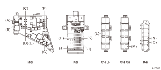
Main fuse box | Headlight relay (HI) | (A) |
Headlight relay (LO) | (B) | |
Fuse 15 A (daytime running light relay) | (C) | |
Fuse 30 A (combination light LH/RH) | (D) | |
Fuse 20 A (spot map light, room light, ignition switch illumination (immobilizer antenna)) | (E) | |
Fuse 15 A (tail and illumination relay, daytime running light relay) | (F) | |
Daytime running light relay | (G) | |
Relay & fuse box | Fuse 10 A (stop light and brake switch, brake relay) | (H) |
Fuse 10A (inhibitor switch, back-up light switch, auto headlight beam leveler CU) | (I) | |
Fuse 15A (front fog light relay*2, front fog light relay LH/RH*1) | (J) | |
Fuse 7.5 A (turn signal & hazard unit) | (K) | |
Relay holder LH (passenger room) | Tail & illumination relay | (L) |
Relay holder RH (passenger room) | Front fog light relay*1 | (M) |
Relay holder (engine compartment) | Front fog light relay RH*2 | (N) |
Front fog light relay LH*2 | (O) |
*1: Model without SRF
*2: Model with SRF
NOTE:
For other related fuses, refer to the wiring diagram. Power Supply Circuit">
 Inspection
LIGHTING SYSTEM > Relay and FuseINSPECTION1. CHECK FUSE1. Remove the fuse and inspect visually.2. If the fuse is blown out, replace the fuse.NOTE:If the fuse is blown again, check the system wiring ...
 Room light
...
Other materials:
Dtc c0044 tcm communication circuit
VEHICLE DYNAMICS CONTROL (VDC) (DIAGNOSTICS) > Diagnostic Procedure with Diagnostic Trouble Code (DTC)DTC C0044 TCM COMMUNICATION CIRCUITDTC detecting condition:No CAN signal from TCM.Trouble symptom:• ABS does not operate.• VDC does not operate.• EyeSight does not operate.STEPC ...
Journey time
The journey time shows the time that has
elapsed since the ignition switch was
turned to the "ON" position.
The journey time indication flashes each
time a complete hour has elapsed. If the
display is giving a reading other than the
journey time, the display switches to the
journey ti ...
Installation
INSTRUMENTATION/DRIVER INFO > Combination MeterINSTALLATIONCAUTION:• Make sure the electrical connector is connected securely.• Make sure that each meter operates normally.• When the combination meter assembly has been replaced, be sure to perform the following operations.– F ...
