Subaru Crosstrek Service Manual: Installation
VEHICLE DYNAMICS CONTROL (VDC) > VDC Control Module and Hydraulic Control Unit (VDCCM&H/U)
INSTALLATION
1. MODELS WITHOUT EyeSight
CAUTION:
• When installing the VDCCM&H/U to the bracket - hydraulic unit, make sure that there is no oil adhered to the bolts and the threads of VDCCM&H/U. If the oil is adhered, degrease it carefully before tightening.
• Connect the VDCCM&H/U connector securely.
• When installing the VDCCM&H/U, replace the damper - hydraulic unit, spacer and nut with new parts.
1. Install the VDC control module & hydraulic control unit (VDCCM&H/U) in the reverse order of removal.
Tightening torque:
Refer to “COMPONENT” of “General Description”. General Description > COMPONENT">
2. Install the air intake boot. Air Intake Boot > INSTALLATION">
3. Connect the battery ground terminal. NOTE">
4. Bleed air from the brake system. Air Bleeding">
5. Perform parameter confirmation, selection, and registration.
NOTE:
• When the VDCCM&H/U is replaced with a new part, be sure to perform the selection • registration operation.
• When the registration has not been performed, the DTC code “Parameter selection error” is detected together with the ABS/EBD/VDC warning light illumination.
(1) Check that the applied model and grade of the relevant vehicle are included. Subaru Select Monitor > OPERATION">
(2) If the applied model and grade of the target vehicle are not included, perform parameter selection and registration. Subaru Select Monitor > OPERATION">
6. Perform “VDC sensor midpoint setting mode”. VDC Control Module and Hydraulic Control Unit (VDCCM&H/U) > ADJUSTMENT">
2. MODELS WITH EyeSight
CAUTION:
• When the VDCCM&H/U components are removed, be sure to perform the installation according to the following procedures to prevent fluid leakage.
• When installing the VDCCM&H/U to the bracket - hydraulic unit, make sure that there is no oil adhered to the bolts and the threads of VDCCM&H/U. If the oil is adhered, degrease it carefully before tightening.
• Be careful not to deform the bracket - hydraulic unit for hose assembly.
• Connect the VDCCM&H/U connector securely.
1. Install the VDCCM&H/U.
NOTE:
Refer to the following figure for tightening torque.
(1) Set the VDCCM&H/U (a) to the bracket - hydraulic unit (b).
(2) Set the hose assembly (c) to the bracket - hydraulic unit (b).
(3) Set pipe A (d) and pipe B (e), and temporarily tighten the flare nuts.
(4) Tighten the VDCCM&H/U (a) and the bracket - hydraulic unit (b).
(5) Tighten the hose assembly (c) and the bracket - hydraulic unit (b).
(6) Tighten pipe A (d) and pipe B (e).
(7) Set the center pipes (f) to hose assembly (c), and temporarily tighten the flare nuts.
(8) Install the hose assembly (c) to the vehicle body.
(9) Tighten the flare nuts of the center pipes (f).
(10) Install the brake pipes (g).
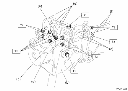
Tightening torque:
T1: 7.5 N·m (0.8 kgf-m, 5.5 ft-lb)
T2: 15 N·m (1.5 kgf-m, 11.1 ft-lb)
T3: 18 N·m (1.8 kgf-m, 13.3 ft-lb)
T4: 19 N·m (1.9 kgf-m, 14.0 ft-lb)
2. Connect the VDCCM&H/U connector.
3. Install the air intake boot. Air Intake Boot > INSTALLATION">
4. Connect the battery ground terminal. NOTE">
5. Bleed air from the brake system. Air Bleeding">
6. Perform parameter confirmation, selection, and registration.
NOTE:
• When the VDCCM&H/U is replaced with a new part, be sure to perform the selection · registration operation.
• When the registration has not been performed, the DTC code “Parameter selection error” is detected together with the ABS/EBD/VDC warning light illumination.
(1) Check that the applied model and grade of the relevant vehicle are included. Subaru Select Monitor > OPERATION">
(2) If the applied model and grade of the target vehicle are not included, perform parameter selection and registration. Subaru Select Monitor > OPERATION">
7. Perform the following VDC setting mode.
• Neutral of Steering Angle Sensor & Lateral G Sensor 0 point setting VDC Control Module and Hydraulic Control Unit (VDCCM&H/U) > ADJUSTMENT">
• Longitudinal G sensor & lateral G sensor 0 point setting VDC Control Module and Hydraulic Control Unit (VDCCM&H/U) > ADJUSTMENT">
 Inspection
VEHICLE DYNAMICS CONTROL (VDC) > VDC Control Module and Hydraulic Control Unit (VDCCM&H/U)INSPECTION1. Check the identification (a) of the VDC control module & hydraulic control unit (VDCCM ...
 Removal
VEHICLE DYNAMICS CONTROL (VDC) > VDC Control Module and Hydraulic Control Unit (VDCCM&H/U)REMOVAL1. MODELS WITHOUT EyeSight1. Disconnect the ground cable from battery. NOTE">2. Remove ...
Other materials:
Using a flat-bed truck
This is the best way to transport your
vehicle. Use the following procedures to
ensure safe transportation.
1. Shift the select lever into the "P" position for CVT models. Shift the shift
lever into the "1st" position for MT models.
2. Pull up the parking brake lever firmly.
3. Secur ...
Dtc u0122 lost communication with vehicle dynamics control module
KEYLESS ACCESS WITH PUSH BUTTON START SYSTEM (DIAGNOSTICS) > Diagnostic Procedure with Diagnostic Trouble Code (DTC)DTC U0122 LOST COMMUNICATION WITH VEHICLE DYNAMICS CONTROL MODULEDetected when CAN data from VDC does not arrive.NOTE:Perform the diagnosis for LAN system. Basic Diagnostic Procedu ...
Brake fluid level warning
This light illuminates when the brake fluid
level has dropped to near the "MIN" level
of the brake fluid reservoir with the ignition
switch in the "ON" position and with the
parking brake fully released.
If the brake system warning light should
illuminate while driving (with the parking
bra ...
