Subaru Crosstrek Service Manual: Installation
REAR SUSPENSION > Rear Sub Frame
INSTALLATION
CAUTION:
• Be sure to use a new self-locking nut.
• Always tighten the bushing in the state where the vehicle is at curb weight and the wheels are in full contact with the ground.
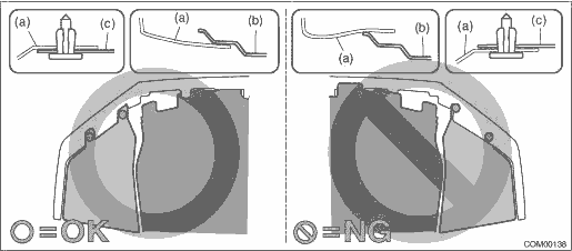
• Install so that the front end of the under cover (b) comes inside the bumper face - front (a), and the front end of the mud guard (c) comes outside the bumper face - front (a).
1. Check the removed parts for wear, damage and crack, and repair or replace them if faulty.
2. Install each part in the reverse order of removal.
Tightening torque:
• Rear suspension parts: General Description > COMPONENT">
• Fuel tank protector: Fuel Tank Protector > REMOVAL">
• Rear disc brake parts: General Description > COMPONENT">
• Parking brake parts: General Description > COMPONENT">
• Exhaust pipe parts: General Description > COMPONENT">
• Propeller shaft parts: Propeller Shaft > INSTALLATION">
3. Install the under cover - front.
Tightening torque:
18 N·m (1.84 kgf-m, 13.3 ft-lb)
4. Bleed air from brake system. Air Bleeding > PROCEDURE">
5. Install the rear wheels.
Tightening torque:
Except for C4 model: 120 N·m (12.24 kgf-m, 88.5 ft-lb)
C4 model: 100 N·m (10.20 kgf-m, 73.8 ft-lb)
6. Inspect the wheel alignment and adjust if necessary.
• Inspection: Wheel Alignment > INSPECTION">
• Adjustment: Wheel Alignment > ADJUSTMENT">
CAUTION:
When the wheel alignment has been adjusted, perform the following VDC setting mode.
– Model without EyeSight: VDC sensor midpoint setting mode VDC Control Module and Hydraulic Control Unit (VDCCM&H/U) > ADJUSTMENT">
– Model with EyeSight: Neutral of Steering Angle Sensor & Lateral G Sensor 0 point setting VDC Control Module and Hydraulic Control Unit (VDCCM&H/U) > ADJUSTMENT">
– Model with EyeSight: Longitudinal G sensor & lateral G sensor 0 point setting VDC Control Module and Hydraulic Control Unit (VDCCM&H/U) > ADJUSTMENT">
7. Connect the battery ground terminal.
8. Perform reinitialization of the auto headlight beam leveler system. (Model with auto headlight beam leveler) Auto Headlight Beam Leveler System > PROCEDURE">
 Removal
REAR SUSPENSION > Rear Sub FrameREMOVAL1. Disconnect the ground cable from battery. NOTE">2. Lift up the vehicle, and then remove the rear wheels.3. Remove the bolts and clips, and remove ...

Other materials:
Dtc u0131 lost communication with power steering control module
LAN SYSTEM (DIAGNOSTICS) > Diagnostic Procedure with Diagnostic Trouble Code (DTC)DTC U0131 LOST COMMUNICATION WITH POWER STEERING CONTROL MODULEDTC DETECTING CONDITION:No data is received from power steering CM.TROUBLE SYMPTOM:Cooperation control with power steering CM does not operate properly. ...
Preparation tool
HVAC SYSTEM (HEATER, VENTILATOR AND A/C) > General DescriptionPREPARATION TOOL1. SPECIAL TOOLILLUSTRATIONTOOL NUMBERDESCRIPTIONREMARKS — SUBARU SELECT MONITOR 4Used for setting of each function and troubleshooting for electrical system.NOTE:For detailed operation procedures of Subaru Select Mon ...
Dtc u1433 invalid data received from eyesight
CONTINUOUSLY VARIABLE TRANSMISSION (DIAGNOSTICS) > Diagnostic Procedure with Diagnostic Trouble Code (DTC)DTC U1433 INVALID DATA RECEIVED FROM EyeSightNOTE:Refer to “LAN SYSTEM (DIAGNOSTICS)” for diagnostic procedure. Basic Diagnostic Procedure">1. OUTLINE OF DIAGNOSIS• ...
