Subaru Crosstrek Service Manual: Installation
POWER ASSISTED SYSTEM (POWER STEERING) > Universal Joint
INSTALLATION
1. Before installation, check the universal joint assembly - steering. Universal Joint > INSPECTION">
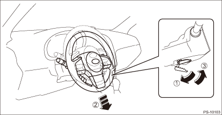
2. Adjust the tilt position of the column assembly - steering to the neutral position and lock the tilt lever.
3. Align the cutout portion (a) at serrated section of the column shaft (c) and yoke (b), then install the universal joint assembly - steering into column shaft.
CAUTION:
Be sure to align the protrusion section (a) of the column shaft side with the cutout (a) of the serration. If another cutout portions (d) are used for alignment, the bolt of the universal joint assembly - steering cannot be assembled.
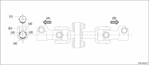
(A) | Column shaft side | (B) | Gearbox side |
4. Install the universal joint assembly - steering to the serrations of the gearbox assembly by matching the alignment marks.
5. Tighten the bolts on the gearbox side first, and then the column shaft side.
CAUTION:
Be sure to follow the tightening order and tightening torque of the universal joint assembly - steering to avoid the steering effort from becoming heavy.
Tightening torque:
24 N·m (2.45 kgf-m, 17.7 ft-lb)
Clearance:
Universal joint assembly - steering coupling to adjacent parts: 15 mm (0.59 in) or more
 Removal
POWER ASSISTED SYSTEM (POWER STEERING) > Universal JointREMOVAL1. Adjust the tilt position of the column assembly - steering to the lowest position and lock the tilt lever.2. Remove the universal j ...
 General diagnostic table Inspection
POWER ASSISTED SYSTEM (POWER STEERING) > General Diagnostic TableINSPECTIONTroublePossible causeCorrective action• Steering effort is heavy in all ranges.• Steering effort is heavy at s ...
Other materials:
Adjustment
MANUAL TRANSMISSION AND DIFFERENTIAL(5MT) > Reverse Check SleeveADJUSTMENT1. NEUTRAL POSITION ADJUSTMENT1. Shift the gear into 3rd gear position.2. Because of the return spring, until the arm contacts the stopper the shifter arm will feel lighter moving towards 1st/2nd gear and heavier towards th ...
Dtc c1351 normal opening valve 1
VEHICLE DYNAMICS CONTROL (VDC) (DIAGNOSTICS) > Diagnostic Procedure with Diagnostic Trouble Code (DTC)DTC C1351 NORMAL OPENING VALVE 1NOTE:For the diagnostic procedure, refer to “DTC C1362 NORMAL CLOSING VALVE 2”. Diagnostic Procedure with Diagnostic Trouble Code (DTC) > DTC C1362 ...
Installation
BRAKE > Rear Disc RotorINSTALLATIONNOTE:Before installation, remove mud and foreign matter from the caliper body assembly.1. Before installation, check the rear disc rotor. Rear Disc Rotor > INSPECTION">2. Install each part in the reverse order of removal.NOTE:When installing the rear ...
