Subaru Crosstrek Service Manual: Installation
POWER ASSISTED SYSTEM (POWER STEERING) > Steering Column
INSTALLATION
CAUTION:
If the steering wheel and steering angle sensor are removed, perform the following VDC setting mode.
– Model without EyeSight: VDC sensor midpoint setting mode VDC Control Module and Hydraulic Control Unit (VDCCM&H/U) > ADJUSTMENT">
– Model with EyeSight: Neutral of Steering Angle Sensor & Lateral G Sensor 0 point setting VDC Control Module and Hydraulic Control Unit (VDCCM&H/U) > ADJUSTMENT">
– Model with EyeSight: Longitudinal G sensor & lateral G sensor 0 point setting VDC Control Module and Hydraulic Control Unit (VDCCM&H/U) > ADJUSTMENT">
1. Install the grommet to the toe board.
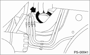
2. Insert the end of the column assembly - steering into the toe board grommet.
3. Tighten the column assembly - steering installation bolt located under the beam COMPL - steering with the tilt lever fixed.
Tightening torque:
20 N·m (2.04 kgf-m, 14.8 ft-lb)
4. Connect all connectors located under the beam COMPL - steering.
5. Install the airbag module. Driver’s Airbag Module > INSTALLATION">
6. Install the knee airbag module. Knee Airbag Module > INSTALLATION">
7. Install the cover assembly - instrument panel LWR driver INN and OUT.
8. Install the universal joint assembly - steering. Universal Joint > INSTALLATION">
CAUTION:
• Always install the universal joint assembly - steering after installing the steering column to avoid damage to the universal joint assembly - steering.
• Be sure to follow the tightening order and tightening torque of the universal joint assembly - steering to avoid the steering effort from becoming heavy.
9. Align the center position of the steering roll connector. Roll Connector > ADJUSTMENT">
10. Install the steering wheel. Steering Wheel > INSTALLATION">
 Removal
POWER ASSISTED SYSTEM (POWER STEERING) > Steering ColumnREMOVALCAUTION:Before handling the airbag system components, always refer to “CAUTION” of “General Description” in &l ...
 Steering wheel
...
Other materials:
Dtc p0335 crankshaft position sensor "a" circuit
ENGINE (DIAGNOSTICS)(H4DO) > Diagnostic Procedure with Diagnostic Trouble Code (DTC)DTC P0335 CRANKSHAFT POSITION SENSOR "A" CIRCUITDTC DETECTING CONDITION:Immediately at fault recognitionTROUBLE SYMPTOM:• Engine stall• Failure of engine to startCAUTION:After servicing or re ...
Inspection
SECURITY AND LOCKS > Rear Door Latch and Door Lock Actuator AssemblyINSPECTION1. LATCHCheck if the latch operates normally.If the cable is faulty, replace the latch & actuator assembly - rear.2. ACTUATOR1. Check door lock operationCheck the door lock operation when battery voltage is applied ...
Dtc b1430 in-vehicle (post evaporator) temperature sensor circuit open
HVAC SYSTEM (AUTO A/C) (DIAGNOSTICS) > Diagnostic Procedure with Diagnostic Trouble Code (DTC)DTC B1430 IN-VEHICLE (POST EVAPORATOR) TEMPERATURE SENSOR CIRCUIT OPENDTC detecting condition:In-vehicle sensor circuit is open.Trouble symptom:In-vehicle air temperature is falsely recognized as 25& ...
