Subaru Crosstrek Service Manual: Installation
PARKING BRAKE > Parking Brake Assembly (Rear Disc Brake)
INSTALLATION
CAUTION:
Be sure the lining surface is free from brake fluid and grease.
1. Apply brake grease to the following locations.
Preparation items:
Brake grease: Dow Corning Molykote 44MA or equivalent
• Six contact surfaces of the parking brake shoe rim and back plate - rear brake
• Contact surface of the parking brake shoe and the anchor pin
• Contact surface of the parking lever assembly - rear and the strut - brake
• Contact surface of the parking brake shoe and the adjuster assembly - rear brake
• Contact surface of the parking brake shoe and the strut - brake
• Contact surface of the parking lever - rear and the parking brake shoe
2. Install the spring washer - rear brake and the lever to the secondary side parking brake shoe pin, and lock the retainer - rear brake securely.
3. Install the cable assembly - parking brake to the lever.
4. Attach the adjuster assembly - rear brake and the spring - adjuster to the parking brake shoe.
NOTE:
Install the adjuster assembly - rear brake with the screw section facing to the direction shown in the figure below.
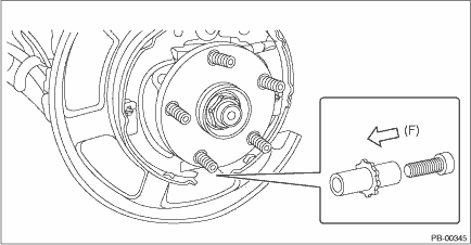
(F) | Left wheel: front side of vehicle, right wheel: rear side of vehicle |
5. Check that the cable assembly - parking brake does not fall from the cable guide.
6. Install the parking brake shoes to the back plate - rear brake with the pins - shoe hold-down and the cups - shoe hold-down.
NOTE:
• Do not reversely install the pin - primary shoe hold-down (a) and the pin - secondary shoe hold-down (b).
• When installing the pin - secondary shoe hold-down (b), face the convex portion to the rear of the vehicle not to contact with the parking lever - rear.
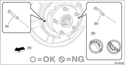
(A) | Front side of vehicle | (B) | Orientation of pin - shoe hold-down relative to the front of the vehicle |
7. Install the strut - brake and the spring - strut to the parking brake shoes.
NOTE:
Install the spring - strut so that it comes towards the front side of the vehicle.
8. Install the return springs on the primary side first, and then the secondary side.
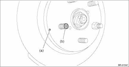
9. Install the brake disc rotor and the brake caliper assembly.
NOTE:
When installing the rear disc rotor, match the alignment mark (a) of the rear disc rotor and the alignment mark (b) of the bolt - hub.
10. Install the brake hose bracket.
Tightening torque:
Refer to “COMPONENT” of “General Description”. General Description > COMPONENT">
11. Adjust the parking brake. Parking Brake Assembly (Rear Disc Brake) > ADJUSTMENT">
12. Install the rear wheels.
Tightening torque:
Except for C4 model: 120 N·m (12.24 kgf-m, 88.5 ft-lb)
C4 model: 100 N·m (10.20 kgf-m, 73.8 ft-lb)
13. If new parking brake shoes are replaced, drive the vehicle to break-in the parking brake lining.
(1) Drive the vehicle at approximately 35 km/h (22 MPH) or more.
(2) While pressing the button of lever assembly - hand brake, pull the lever assembly - hand brake with a force of 150 N (15.3 kgf, 33.7 lbf).
(3) Drive the vehicle for about 200 m (0.12 mile) in this condition.
(4) Wait 5 to 10 minutes for the parking brake to cool down. Repeat steps (1) through (3) again.
(5) After breaking-in, re-adjust the parking brakes.
 Inspection
PARKING BRAKE > Parking Brake Assembly (Rear Disc Brake)INSPECTION1. Measure the inner diameter of the rear disc rotor. If scoring or worn is found on the disc, replace the rear disc rotor.Disc rot ...

Other materials:
Front seatbelts
1. Adjust the seat position according to
the following procedure.
Driver's seat: Adjust the seatback to the
upright position. Move the seat as far from
the steering wheel as practical while still
maintaining full vehicle control.
Front passenger's seat: Adjust the seatback
to the upright ...
Using the voice command system
Steering switch
Talk switch
Action
Function
Press
Start the voice command
system.
Press and hold
Cancel voice recognition.
Microphone
Type A
Type B
It is unnecessary to speak directly into the
microphone when giving a command.
NOTE
Wait ...
Installation
MANUAL TRANSMISSION AND DIFFERENTIAL(5MT) > Transfer Driven GearINSTALLATION1. Install the taper roller bearing (transfer case side) outer race.(A)Taper roller bearing (transfer case side) outer race(B)Transfer case2. Apply a coat of grease to the taper roller bearing (transfer case side) of tran ...
