Subaru Crosstrek Service Manual: Installation
MECHANICAL(H4DO) > Engine Assembly
INSTALLATION
1. Install the engine mounting onto the engine.
Tightening torque:
35 N·m (3.6 kgf-m, 25.8 ft-lb)
2. Apply a small amount of grease to splines of main shaft. (MT model)
Grease:
NICHIMOLY N-130 or equivalent
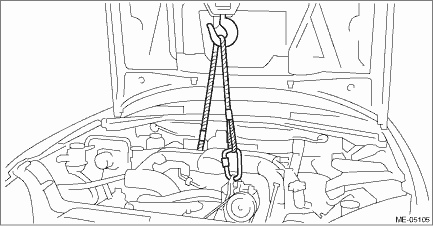
3. Position the engine in engine compartment and align it with transmission.
NOTE:
Be careful not to damage adjacent parts or body panels with crank pulley, oil level gauge, etc.
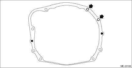
4. Install the bolts which hold upper side of transmission to engine.
Tightening torque:
50 N·m (5.1 kgf-m, 36.9 ft-lb)
• CVT model
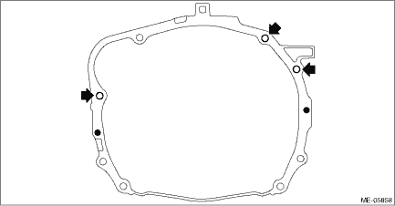
• MT model
5. Remove the lifting device and wire ropes.
6. Remove the garage jack.
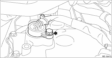
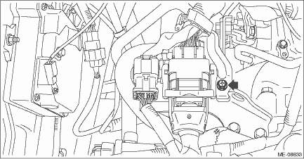
7. Remove the bolt and turn the transmission harness counterclockwise to install the transmission harness to the control valve body. (CVT model)
Tightening torque:
7 N·m (0.7 kgf-m, 5.2 ft-lb)
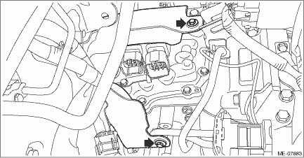
8. Install the bolt which holds the transmission harness stay. (CVT model)
Tightening torque:
7 N·m (0.7 kgf-m, 5.2 ft-lb)
9. Install the transmission case cover. (CVT model)
Tightening torque:
8 N·m (0.8 kgf-m, 5.9 ft-lb)
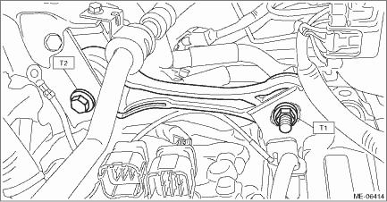
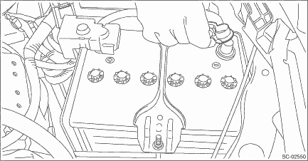
10. Install the pitching stopper.
Tightening torque:
T1: 50 N·m (5.1 kgf-m, 36.9 ft-lb)
T2: 58 N·m (5.9 kgf-m, 42.8 ft-lb)
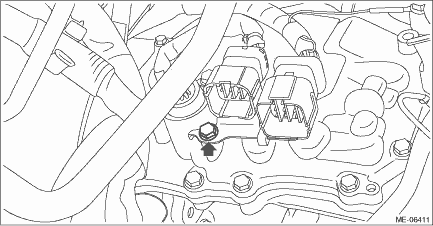
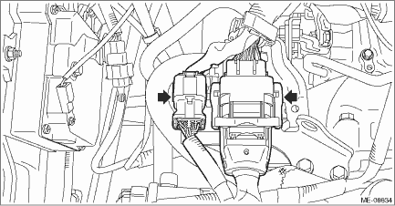
11. Connect the transmission radio ground terminal (C) to the vehicle body, and connect the bulkhead harness connector to the transmission harness connector (A) and the inhibitor harness connector (B). (CVT model)
Tightening torque:
13 N·m (1.3 kgf-m, 9.6 ft-lb)
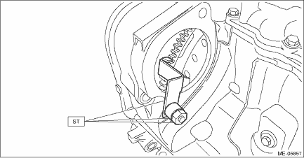
12. Remove the ST from torque converter clutch case. (CVT model)
NOTE:
Be careful not to drop the ST into the torque converter clutch case when removing the ST.
| ST 498277200 | STOPPER SET |
13. Install the torque converter clutch to drive plate. (CVT model)
(1) Insert the wrench into the crank pulley bolt, and rotate the crank pulley to attach the four bolts securing the torque converter clutch to the drive plate.
NOTE:
Be careful not to drop bolts into the torque converter clutch case.
Tightening torque:
25 N·m (2.5 kgf-m, 18.4 ft-lb)
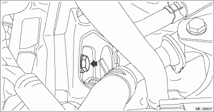
(2) Fit the plug to service hole.
(3) Install the throttle body. Throttle Body > INSTALLATION">
14. Install the starter. Starter > INSTALLATION">
15. Lift up the vehicle.
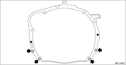
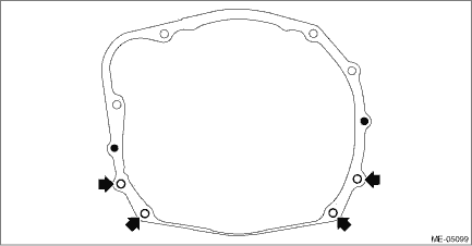
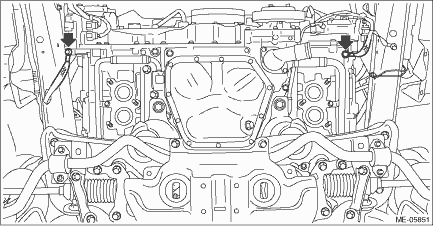
16. Install the bolts and nuts which hold lower side of the transmission to engine.
Tightening torque:
50 N·m (5.1 kgf-m, 36.9 ft-lb)
• CVT model
• MT model
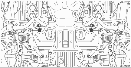
17. Install the nuts which hold the engine mounting to the crossmember. (CVT model)
NOTE:
• Make sure that locators (A) of the engine mounting are securely inserted.
• Use a new nut.
Tightening torque:
60 N·m (6.1 kgf-m, 44.3 ft-lb)
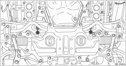
18. Install the nuts which hold the engine mounting to the crossmember. (MT model)
NOTE:
Use a new nut.
Tightening torque:
60 N·m (6.1 kgf-m, 44.3 ft-lb)
19. Connect the ground cable.
Tightening torque:
7.5 N·m (0.8 kgf-m, 5.5 ft-lb)
20. Install the front exhaust pipe. Front Exhaust Pipe > INSTALLATION">
21. Lower the vehicle.
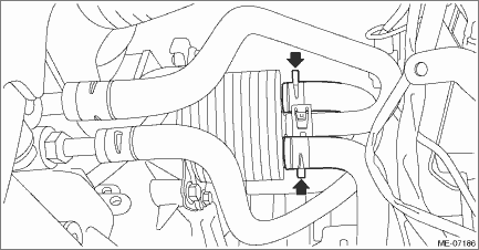
22. Install the CVTF cooler (with warmer feature) to the transmission. (CVT model)
Tightening torque:
23 N·m (2.3 kgf-m, 17.0 ft-lb)
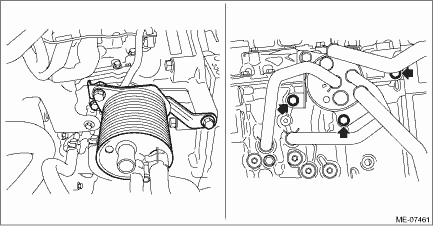
23. Connect the water hose to the CVTF cooler (with warmer feature). (CVT model)
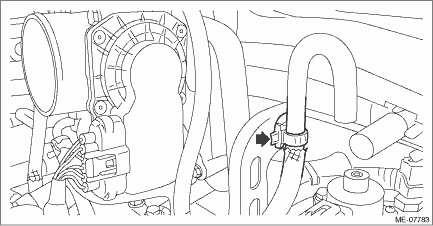
24. Connect the fuel delivery tube and evaporation hose.
(1) Connect the evaporation hose to fuel pipe assembly.
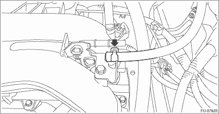
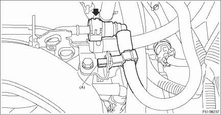
(2) Connect the quick connector on the fuel delivery tube to the fuel pipe assembly, and fix the fuel delivery tube using clip (A).
CAUTION:
• Check that there is no damage or dust on the quick connector. If necessary, clean the seal surface of the pipe.
• When connecting the quick connector, make sure to insert it all the way in before locking the slider.
• When it is difficult to lock the slider, check that the connector is fully inserted.
• After locking the slider, check that the quick connector is securely connected.
NOTE:
Connect the quick connector as shown in the figure.
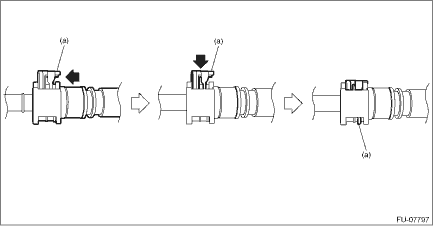
(a) | Slider |
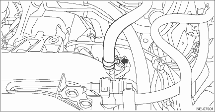
25. Connect the heater inlet hose and heater outlet hose.
NOTE:
Be careful not to mix up the heater inlet hose and the heater outlet hose when connecting them.
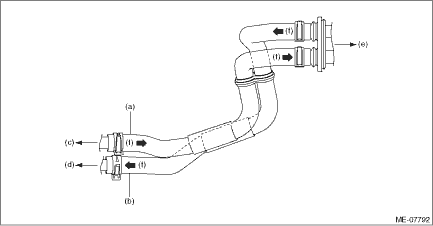
(a) | Heater inlet hose | (c) | To water pipe ASSY | (e) | To heater core ASSY |
(b) | Heater outlet hose | (d) | To water pipe LH | (f) | Engine coolant flow |
26. Connect the A/C pressure hose to A/C compressor. Hose and Pipe > INSTALLATION">
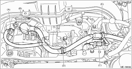
27. Place the generator code and install the generator cord to the clip (D) and clip (E).
28. Connect connector (A) and terminal (B) to the generator, and connect connector (C) to A/C compressor.
Tightening torque:
15.5 N·m (1.6 kgf-m, 11.4 ft-lb)
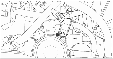
29. Install the generator cord stay to the chain cover.
NOTE:
Install the generator cord stay so that the folded end (a) touches the chain cover boss.
Tightening torque:
8 N·m (0.8 kgf-m, 5.9 ft-lb)
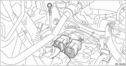
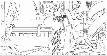
30. Connect the engine harness connector.
(1) Connect the bulkhead harness connector to the engine harness connector (black) and engine harness connector (brown).
(2) Install the bolt which secures the bulkhead harness connector bracket.
Tightening torque:
7.5 N·m (0.8 kgf-m, 5.5 ft-lb)
31. Secure the air breather hose to the engine rear hanger using clip. (MT model)
32. Connect the brake booster vacuum hose to the intake manifold.
33. Install the radiator. Radiator > INSTALLATION">
34. Install the air cleaner case (rear) together with the air cleaner element. Air Cleaner Case > INSTALLATION">
35. Secure the bulkhead wiring harness with clip (A) and connect the connector to the mass air flow and intake air temperature sensor.
36. Install the air intake boot. Air Intake Boot > INSTALLATION">
37. Install the air intake duct. Air Intake Duct > INSTALLATION">
38. Connect the battery ground terminal.
39. Charge the A/C system with refrigerant. Refrigerant Charging Procedure > PROCEDURE">
40. Fill engine coolant. Engine Coolant > REPLACEMENT">
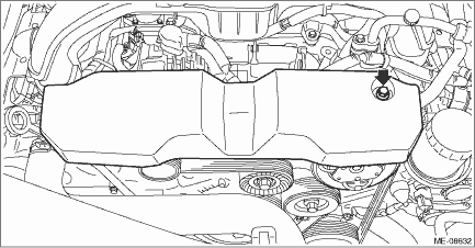
41. Install the V-belt cover.
Tightening torque:
7 N·m (0.7 kgf-m, 5.2 ft-lb)
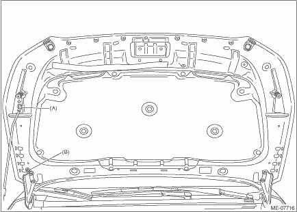
42. Change the front hood stay position from (B) to (A).
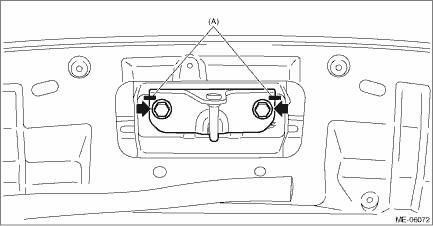
43. Install the front hood striker to the front hood by aligning the alignment marks (A), and close the front hood.
Tightening torque:
33 N·m (3.4 kgf-m, 24.3 ft-lb)
 Removal
MECHANICAL(H4DO) > Engine AssemblyREMOVAL1. Open the front hood, and make alignment marks (A) on both the front hood and the front hood striker by using a marker pen.2. Remove the front hood strike ...
 Engine mounting
...
Other materials:
Dtc c2424 transmitter 4 battery voltage low
TIRE PRESSURE MONITORING SYSTEM (DIAGNOSTICS) > Diagnostic Procedure with Diagnostic Trouble Code (DTC)DTC C2424 TRANSMITTER 4 BATTERY VOLTAGE LOWDTC DETECTING CONDITION:Detected when power supply voltage failure signal is received from each transmitter.TROUBLE SYMPTOM:Tire pressure warning light ...
Adjustment
CONTROL SYSTEMS > Select CableADJUSTMENT1. Shift the select lever to “N” range.2. Lift up the vehicle.3. Remove the center exhaust pipe. Center Exhaust Pipe > REMOVAL">4. Remove the center exhaust cover.5. Loosen the adjusting nuts on both sides.(A)Adjusting nut A(B)Adjust ...
Rear wiring harness Location
WIRING SYSTEM > Rear Wiring HarnessLOCATIONConnectorConnecting toNo.PoleColorAreaNo.DescriptionR120C-1B97Bulkhead wiring harnessR320C-3B99R41BlackB-4 Parking brake switchR520C-3B92Bulkhead wiring harnessR93C-5 Front door switch LHR108B-5D22Rear door cord LHR123B-2 Front door switch RHR138B-3D28Re ...
