Subaru Crosstrek Service Manual: Installation
MECHANICAL(H4DO) > Cam Carrier
INSTALLATION
1. CAM CARRIER RH
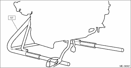
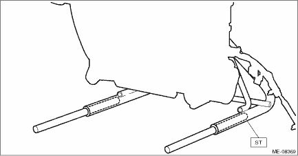
1. Insert the steel rods into ST, and set the engine so that the camshaft RH is facing up.
CAUTION:
• If the engine is standing on one side without inserting the steel rod into ST, engine may lose balance and fall down. Be sure to insert the steel rod into ST to extend the length.
• Use the steel rod with enough strength.
• Be careful not to pinch the engine harness with ST.
| ST 499817100 | ENGINE STAND |
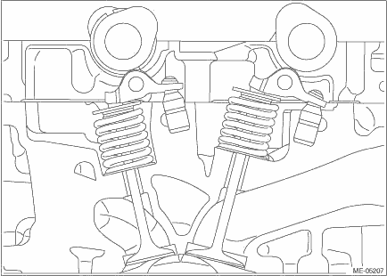
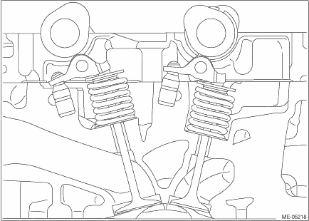
2. Apply engine oil to the valve shim and the roller rocker arm pivot, and install the valve shim and the roller rocker arm pivot to the cylinder head RH.
3. Apply engine oil to the O-ring and the roller rocker arm, and install the O-ring and the roller rocker arm to the cylinder head RH.
NOTE:
Use new O-rings.
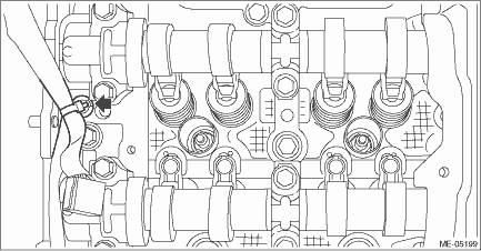
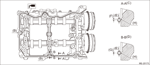
4. Apply liquid gasket to the mating surface of cam carrier RH as shown in the figure.
NOTE:
• Before applying liquid gasket, degrease the old liquid gasket seal surface of the cylinder head RH and cam carrier RH.
• Install within 5 min. after applying liquid gasket.
Liquid gasket:
THREE BOND 1217G (Part No. K0877Y0100), THREE BOND 1217H or equivalent
Liquid gasket applying diameter:
3.1±0.5 mm (0.1220±0.0197 in)
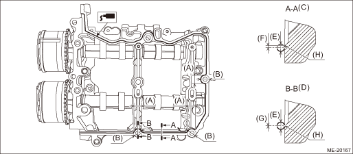
(A) | Range A | (D) | Liquid gasket applying position of mating surfaces of range A | (G) | 0±0.5 mm (0±0.0197 in) |
(B) | φ18 mm (0.7087 in) | (E) | φ3.1±0.5 mm (0.1220±0.0197 in) | (H) | Chamfer edge |
(C) | Liquid gasket applying position of mating surfaces other than range A | (F) | 1 mm (0.0394 in) or less |
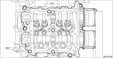
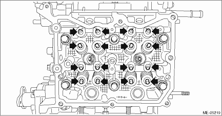
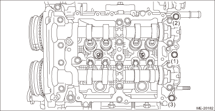
5. Install the cam carrier RH to the cylinder head RH.
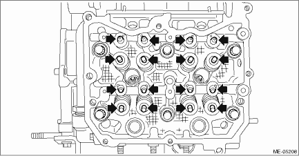
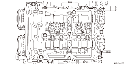
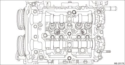
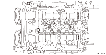
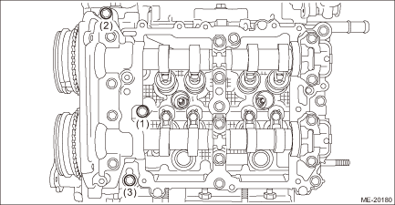
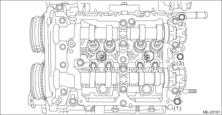
(1) Mount the cam carrier RH, then tighten all bolts with a torque of 18 N·m (1.8 kgf-m, 13.3 ft-lb) in numerical order as shown in the figure.
NOTE:
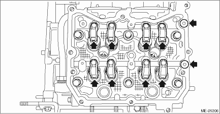
Set the intake camshaft RH and the exhaust camshaft RH to the zero-lift position.
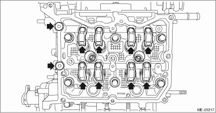
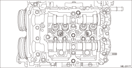
(2) Loosen the bolts (3 places) by 180° in numerical order as shown in the figure.
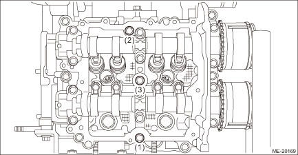
(3) Tighten the bolts (3 places) with a torque of 18 N·m (1.8 kgf-m, 13.3 ft-lb) in numerical order as shown in the figure.
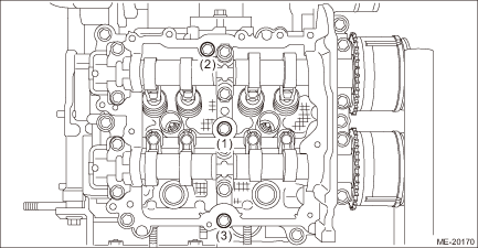
(4) Loosen the bolts (3 places) by 180° in numerical order as shown in the figure.
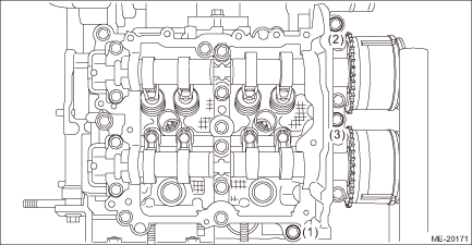
(5) Tighten the bolts (3 places) with a torque of 18 N·m (1.8 kgf-m, 13.3 ft-lb) in numerical order as shown in the figure.
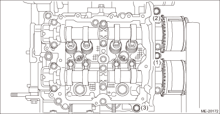
(6) Loosen the bolts (3 places) by 180° in numerical order as shown in the figure.
(7) Tighten the bolts (3 places) with a torque of 18 N·m (1.8 kgf-m, 13.3 ft-lb) in numerical order as shown in the figure.
NOTE:
After tightening, if the liquid gasket is squeezed out onto the seal surface of the chain cover, completely remove any squeezed-out liquid gasket.
6. Set the part so that the intake manifold is on the upper side.
7. Install the cam sprocket RH. Cam Sprocket > INSTALLATION">
NOTE:
This procedure is required only when the cam carrier RH is removed for disassembly.
8. Check the cam clearance. Cam Clearance > INSPECTION">
9. Install the timing chain RH. Timing Chain Assembly > INSTALLATION">
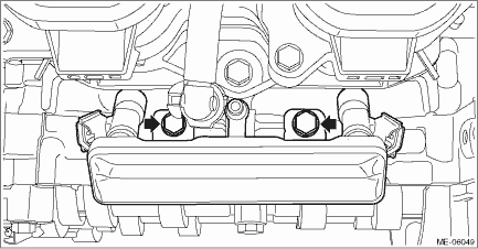
10. Install the fuel pipe RH and the fuel injector RH.
(1) Install the fuel pipe RH and the fuel injector RH, and install the bolts which secure the fuel pipe RH.
NOTE:
• Use new O-rings, rubbers, seal rings and fuel injector holder.
• Refer to “Fuel Injector” for fuel injector holder removal and installation. Fuel Injector > REMOVAL">
Tightening torque:
6.4 N·m (0.7 kgf-m, 4.7 ft-lb)
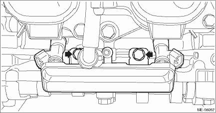
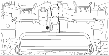
(2) Connect the quick connector to the fuel pipe RH.
CAUTION:
• Check that there is no damage or dust on the quick connector. If necessary, clean the seal surface of the pipe.
• When connecting the quick connector, make sure to insert it all the way in before locking the slider.
• When it is difficult to lock the slider, check that the connector is fully inserted.
• After locking the slider, check that the quick connector is securely connected.
NOTE:
Connect the quick connector as shown in the figure.
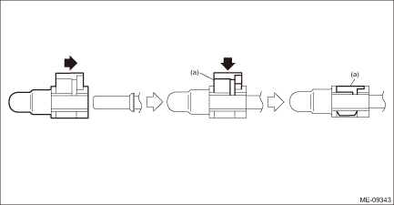
(a) | Slider |
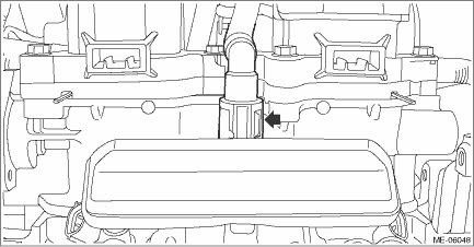
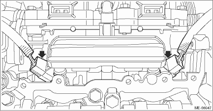
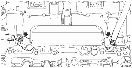
(3) Connect the connectors to the fuel injector RH.
11. Install the water pipe assembly RH. Water Pipe Assembly > INSTALLATION">
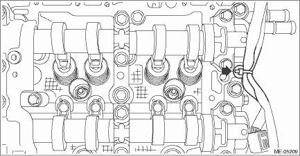
12. Secure the engine harness to the cam carrier RH with a clip.
13. Install the rocker cover RH. Rocker Cover > INSTALLATION">
14. Install the chain cover. Chain Cover > INSTALLATION">
15. Install the engine to the vehicle. Engine Assembly > INSTALLATION">
2. CAM CARRIER LH
1. Insert the steel rods into ST, and set the engine so that the camshaft LH is facing up.
CAUTION:
• If the engine is standing on one side without inserting the steel rod into ST, engine may lose balance and fall down. Be sure to insert the steel rod into ST to extend the length.
• Use the steel rod with enough strength.
• Be careful not to pinch the engine harness with ST.
| ST 499817100 | ENGINE STAND |
2. Apply engine oil to the valve shim and the roller rocker arm pivot, and install the valve shim and the roller rocker arm pivot to the cylinder head LH.
3. Apply engine oil to the O-ring and the roller rocker arm, and install the O-ring and the roller rocker arm to the cylinder head LH.
NOTE:
Use new O-rings.
4. Apply liquid gasket to the mating surface of cam carrier LH as shown in the figure.
NOTE:
• Before applying liquid gasket, degrease the old liquid gasket seal surface of the cylinder head LH and cam carrier LH.
• Install within 5 min. after applying liquid gasket.
Liquid gasket:
THREE BOND 1217G (Part No. K0877Y0100), THREE BOND 1217H or equivalent
Liquid gasket applying diameter:
3.1±0.5 mm (0.1220±0.0197 in)
(A) | Range A | (D) | Liquid gasket applying position of mating surfaces of range A | (G) | 0±0.5 mm (0±0.0197 in) |
(B) | φ18 mm (0.7087 in) | (E) | φ3.1±0.5 mm (0.1220±0.0197 in) | (H) | Chamfer edge |
(C) | Liquid gasket applying position of mating surfaces other than range A | (F) | 1 mm (0.0394 in) or less |
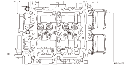
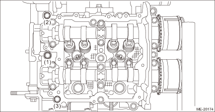
5. Install the cam carrier LH to the cylinder head LH.
(1) Mount the cam carrier LH, then tighten all bolts with a torque of 18 N·m (1.8 kgf-m, 13.3 ft-lb) in numerical order as shown in the figure.
NOTE:
Set the intake camshaft LH and the exhaust camshaft LH to the zero-lift position.
(2) Loosen the bolts (3 places) by 180° in numerical order as shown in the figure.
(3) Tighten the bolts (3 places) with a torque of 18 N·m (1.8 kgf-m, 13.3 ft-lb) in numerical order as shown in the figure.
(4) Loosen the bolts (3 places) by 180° in numerical order as shown in the figure.
(5) Tighten the bolts (3 places) with a torque of 18 N·m (1.8 kgf-m, 13.3 ft-lb) in numerical order as shown in the figure.
(6) Loosen the bolts (3 places) by 180° in numerical order as shown in the figure.
(7) Tighten the bolts (3 places) with a torque of 18 N·m (1.8 kgf-m, 13.3 ft-lb) in numerical order as shown in the figure.
NOTE:
After tightening, if the liquid gasket is squeezed out onto the seal surface of the chain cover, completely remove any squeezed-out liquid gasket.
6. Set the part so that the intake manifold is on the upper side.
7. Install the cam sprocket LH. Cam Sprocket > INSTALLATION">
NOTE:
This procedure is required only when the cam carrier LH is removed for disassembly.
8. Check the cam clearance. Cam Clearance > INSPECTION">
9. Install timing chain LH. Timing Chain Assembly > INSTALLATION">
10. Install the fuel pipe LH and the fuel injector LH.
(1) Install the fuel pipe LH and the fuel injector LH, and install the bolts which secure the fuel pipe LH.
• Use new O-rings, rubbers, seal rings and fuel injector holder.
• Refer to “Fuel Injector” for fuel injector holder removal and installation. Fuel Injector > REMOVAL">
Tightening torque:
6.4 N·m (0.7 kgf-m, 4.7 ft-lb)
(2) Connect the quick connector to the fuel pipe LH.
CAUTION:
• Check that there is no damage or dust on the quick connector. If necessary, clean the seal surface of the pipe.
• When connecting the quick connector, make sure to insert it all the way in before locking the slider.
• When it is difficult to lock the slider, check that the connector is fully inserted.
• After locking the slider, check that the quick connector is securely connected.
NOTE:
Connect the quick connector as shown in the figure.
(a) | Slider |
(3) Connect the connectors to the fuel injector LH.
11. Install the water pipe assembly LH. Water Pipe Assembly > INSTALLATION">
12. Secure the engine harness to the cam carrier LH with a clip.
13. Install the rocker cover LH. Rocker Cover > INSTALLATION">
14. Install the chain cover. Chain Cover > INSTALLATION">
15. Install the engine to the vehicle. Engine Assembly > INSTALLATION">
 Inspection
MECHANICAL(H4DO) > Cam CarrierINSPECTION1. Visually check the cam carrier filter, and if clogging is found, replace with a new part.2. Check the camshaft journals for damage and wear. Replace the c ...
 Cam clearance
...
Other materials:
Shift lock release
If the select lever cannot be operated, turn
the ignition switch back to the "ON"
position then move the select lever to the
"P" position with the select lever button
pressed and brake pedal depressed.
If the select lever does not move after
performing the above procedure, perform
the follo ...
Dtc b2810 incompatible with eyesight (combination meter)
EyeSight (DIAGNOSTICS) > Diagnostic Procedure with Diagnostic Trouble Code (DTC)DTC B2810 INCOMPATIBLE WITH EyeSight (COMBINATION METER)Detected when the combination meter, which is not designed exclusively for EyeSight is installed.DTC DETECTING CONDITION:Incorrect specifications of combination ...
Diagnostic procedure with cancel code Dtc b2328 rear radar internal failure (radar misalignment)
Blind Spot Detection/Rear Cross Traffic Alert (DIAGNOSTICS) > Diagnostic Procedure with Cancel CodeDTC B2328 REAR RADAR INTERNAL FAILURE (RADAR MISALIGNMENT)DETECTING CONDITION:• Excessive impact was given to the installation area of the radar sensor, which resulted in deviation of the rada ...
