Subaru Crosstrek Service Manual: Installation
MANUAL TRANSMISSION AND DIFFERENTIAL(5MT) > Manual Transmission Assembly
INSTALLATION
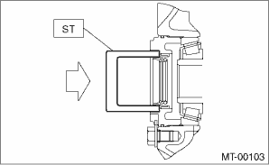
1. Replace the differential side retainer oil seal. Differential Side Retainer Oil Seal > REPLACEMENT">
NOTE:
• Be sure to replace the oil seal after removing the front drive shaft.
• When a new oil seal has been installed, replacement is not required.
| ST 18675AA000 | DIFFERENTIAL SIDE OIL SEAL INSTALLER |
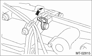
2. Strike and bend the transmission hanger of transmission rear with a rubber hammer etc. so that it gets in contact with the transmission case.
CAUTION:
Do not apply excessive load or impact to the transmission case.
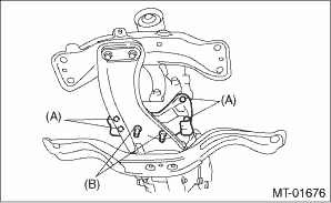
3. Install the transmission cushion rubber to the transmission, and tighten the bolt (A).
4. Install the transmission cushion rubber to the center crossmember, and temporarily tighten the nut (B).
Tightening torque:
Bolt (A)
35 N·m (3.6 kgf-m, 25.8 ft-lb)
5. Install the transmission assembly onto the engine.
(1) Lift up the transmission gradually using a transmission jack.
(2) Engage at the spline section.
NOTE:
Be careful not to hit the main shaft against the clutch cover.
6. While raising the transmission jack, loosen the turnbuckle of the ST, and set the engine unit to the original position.
7. Install the front crossmember and rear crossmember.
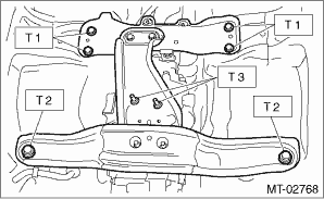
8. Tighten the transmission cushion rubber mounting nut.
Tightening torque:
T1: 70 N·m (7.1 kgf-m, 51.6 ft-lb)
T2: 140 N·m (14.3 kgf-m, 103.3 ft-lb)
T3: 35 N·m (3.6 kgf-m, 25.8 ft-lb)
9. Take out the transmission jack.
10. Tighten the bolts and nuts which hold the lower side of transmission to the engine.
Tightening torque:
50 N·m (5.1 kgf-m, 36.9 ft-lb)
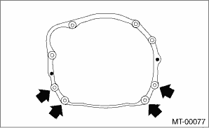
11. Lower the vehicle.
12. Install the starter. Starter > INSTALLATION">
13. Tighten the bolts which hold the upper side of the transmission to the engine.
Tightening torque:
50 N·m (5.1 kgf-m, 36.9 ft-lb)
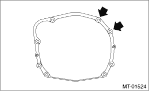
14. Remove the ST.
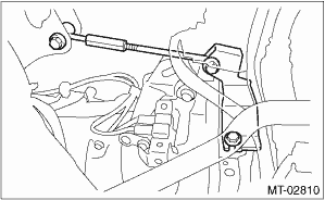
15. Install the ground cable.
Tightening torque:
19 N·m (1.9 kgf-m, 14.0 ft-lb)
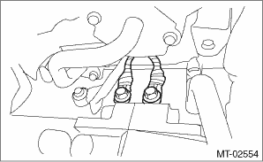
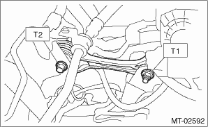
16. Install the pitching stopper.
Tightening torque:
T1: 50 N·m (5.1 kgf-m, 36.9 ft-lb)
T2: 58 N·m (5.9 kgf-m, 42.8 ft-lb)
17. Lift up the vehicle.
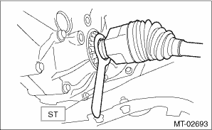
18. Set the ST to differential side retainer.
| ST 28399SA010 | OIL SEAL PROTECTOR |
19. Replace the circlip of the drive shaft with a new part.
20. Install the front drive shaft and remove ST.
| ST 28399SA010 | OIL SEAL PROTECTOR |
21. Insert the front arm ball joint and tighten the mounting bolt.
Tightening torque:
50 N·m (5.1 kgf-m, 36.9 ft-lb)
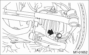
(A) | Front arm |
(B) | Ball joint |
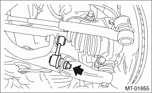
22. Install the stabilizer link.
Tightening torque:
60 N·m (6.1 kgf-m, 44.3 ft-lb)
23. Attach the gear shift rod and stay.
(1) Install the gear shift rod.
NOTE:
Use a new self-locking nut.
Tightening torque:
12 N·m (1.2 kgf-m, 8.9 ft-lb)
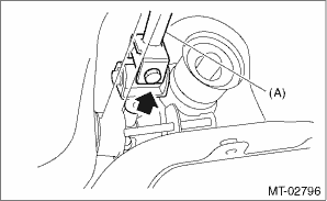
(A) | Gear shift rod |
(2) Install the stay.
NOTE:
Use a new self-locking nut.
Tightening torque:
18 N·m (1.8 kgf-m, 13.3 ft-lb)
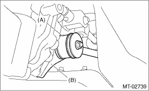
(A) | Stay |
(B) | Shift bracket |
24. Install the propeller shaft. Propeller Shaft > INSTALLATION">
25. Install the hanger bracket.
Tightening torque:
23 N·m (2.3 kgf-m, 17.0 ft-lb)
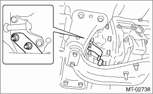
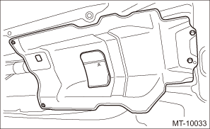
26. Install the center exhaust cover.
Tightening torque:
18 N·m (1.8 kgf-m, 13.3 ft-lb)
27. Install the center exhaust pipe. Center Exhaust Pipe > INSTALLATION">
28. Install the front under cover. Front Under Cover > INSTALLATION">
29. Lower the vehicle.
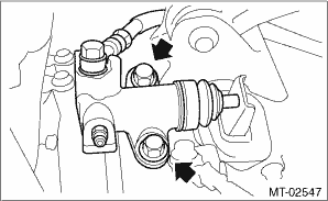
30. Install the operating cylinder.
Tightening torque:
37 N·m (3.8 kgf-m, 27.3 ft-lb)
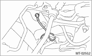
31. Install the transmission radio ground cord terminal.
Tightening torque:
13 N·m (1.3 kgf-m, 9.6 ft-lb)
32. Install the engine hanger rear.
Tightening torque:
21 N·m (2.1 kgf-m, 15.5 ft-lb)
33. Install the air breather hose.
34. Connect the engine harness connector, then attach the harness bracket.
Tightening torque:
7.5 N·m (0.8 kgf-m, 5.5 ft-lb)
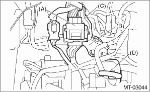
(A) | Engine harness connectors |
(B) | Engine hanger rear |
(C) | Harness bracket |
(D) | Air breather hose |
35. Connect the following connectors and secure the clip.
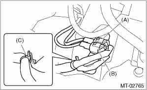
(A) | Neutral position switch connector (brown) |
(B) | Back-up light switch connector (gray) |
(C) | Clip |
36. Pour in transmission gear oil and check the oil level. Transmission Gear Oil">
37. Install the air intake boot. Air Intake Boot > INSTALLATION">
38. Install the front tires.
39. Connect the battery ground terminal.
 Removal
MANUAL TRANSMISSION AND DIFFERENTIAL(5MT) > Manual Transmission AssemblyREMOVAL1. Disconnect the ground cable from battery.2. Remove the clip (A) from the air intake boot.3. Loosen the clamp (B) co ...
Other materials:
Dtc p0068 map/maf - throttle position correlation
ENGINE (DIAGNOSTICS)(H4DO) > Diagnostic Procedure with Diagnostic Trouble Code (DTC)DTC P0068 MAP/MAF - THROTTLE POSITION CORRELATIONDTC detecting condition:Detected when two consecutive driving cycles with fault occur.CAUTION:After servicing or replacing faulty parts, perform Clear Memory Mode ...
Tire pressure warning light does not come off
TIRE PRESSURE MONITORING SYSTEM (DIAGNOSTICS) > Tire Pressure Warning Light / Trouble Indicator Light Illumination PatternTIRE PRESSURE WARNING LIGHT DOES NOT COME OFFDETECTING CONDITION:• Defective combination meter• Tires pressure drop• Transmitter ID not registeredTROUBLE SYM ...
Installation
PARKING BRAKE > Parking Brake CableINSTALLATION1. Install each part in the reverse order of removal.Tightening torque:Cable clamp: 18 N·m (1.84 kgf-m, 13.3 ft-lb)Rear wheel: Except for C4 model120 N·m (12.24 kgf-m, 88.5 ft-lb)Rear wheel: C4 model100 N·m (10.20 kgf-m, 73.8 ft- ...

