Subaru Crosstrek Service Manual: Installation
FUEL INJECTION (FUEL SYSTEMS)(H4DO) > Fuel Sub Level Sensor
INSTALLATION
1. Install the fuel sub level sensor to the fuel tank.
(1) Make sure the sealing portion is free from fuel or foreign matter before installation.
(2) Align the cutout (B) as shown in the figure, and install the fuel sub level sensor upper plate cushion to the fuel sub level sensor upper plate.
(3) Align the cutout of the fuel sub level sensor upper plate with the protrusion (B) of the fuel sub level sensor as shown in the figure, and install the fuel sub level sensor upper plate from the upper side of the fuel sub level sensor.
(4) Install the gasket from the lower side of the fuel sub level sensor so that the protrusion (B) of the fuel sub level sensor and the protrusion (A) of the gasket are positioned as shown in the figure.
NOTE:
Use a new gasket.
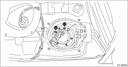
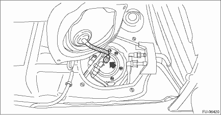
(5) Install the fuel sub level sensor to the fuel tank in the direction shown in the figure, and tighten the nuts to the specified torque in the order as shown in the figure.
CAUTION:
Set the arm and float of the fuel sub level sensor while paying attention to prevent them from contacting the fuel tank. If the arm of the fuel sub level sensor is bent, the fuel gauge may not read correctly.
Tightening torque:
4.4 N·m (0.4 kgf-m, 3.2 ft-lb)
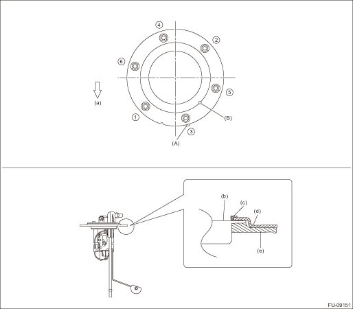
(a) | Front side of vehicle | (c) | Fuel sub level sensor upper plate cushion | (e) | Gasket |
(b) | Fuel sub level sensor | (d) | Fuel sub level sensor upper plate |
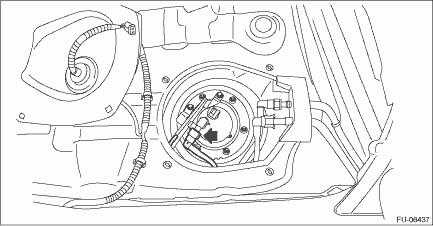
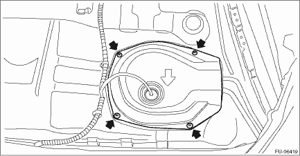
2. Install the fuel sub level sensor protector, and install the rubber cap (A).
Tightening torque:
4.4 N·m (0.4 kgf-m, 3.2 ft-lb)
3. Connect the quick connector of the jet pump tube.
CAUTION:
• Check that there is no damage or dust on the quick connector. If necessary, clean the seal surface of the pipe.
• When connecting the quick connector, make sure to insert it all the way in before locking the slider.
• When it is difficult to lock the slider, check that the connector is fully inserted.
• After locking the slider, check again that the quick connector is securely connected.
NOTE:
Connect the quick connector as shown in the figure.
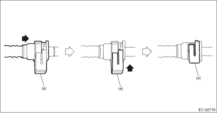
(a) | Slider |
4. Connect the connector to the fuel sub level sensor.
5. Install the service hole cover of fuel sub level sensor.
6. Install the rear seat cushion. Rear Seat > INSTALLATION">
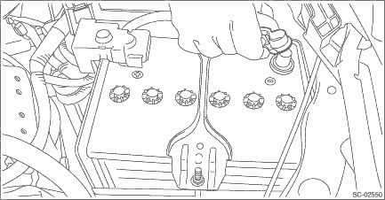
7. Connect the battery ground terminal.
 Removal
FUEL INJECTION (FUEL SYSTEMS)(H4DO) > Fuel Sub Level SensorREMOVALWARNING:Place “NO OPEN FLAMES” signs near the working area.CAUTION:• Be careful not to spill fuel.• Catch t ...
 Fuel tank
...
Other materials:
Push button start system Wiring diagram
WIRING SYSTEM > Push Button Start SystemWIRING DIAGRAM ...
Installation
FUEL INJECTION (FUEL SYSTEMS)(H4DO) > Intake ManifoldINSTALLATION1. Install the engine wiring harness. Engine Wiring Harness > INSTALLATION">2. Install the intake manifold to the tumble generator valve assembly.NOTE:Use a new gasket.Tightening torque:8.3 N·m (0.8 kgf-m, 6.1 ft- ...
Wiring diagram
WIPER AND WASHER SYSTEMS > Wiper and Washer SystemWIRING DIAGRAM1. WIPER AND WASHER (FRONT)Refer to “Front Wiper and Washer System” in the wiring diagram. Front Wiper and Washer System > WIRING DIAGRAM">2. WIPER AND WASHER (REAR)Refer to “Rear Wiper and Washer System ...
