Subaru Crosstrek Service Manual: Installation
EMISSION CONTROL (AUX. EMISSION CONTROL DEVICES)(H4DO) > EGR Cooler
INSTALLATION
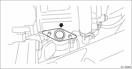
1. Set the gasket to the stud bolt.
NOTE:
Use a new gasket.
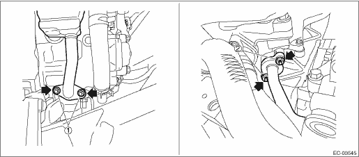
2. Temporarily tighten the bolts securing the EGR cooler to the EGR control valve and the cylinder head RH, and tighten in numerical order.
NOTE:
Use a new gasket.
Tightening torque:
9 N·m (0.9 kgf-m, 6.6 ft-lb)
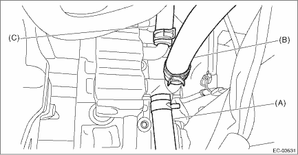
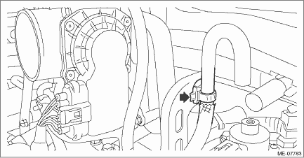
3. Connect the engine coolant hose (A), engine coolant hose (B) (CVT model) and engine coolant hose (C) to the EGR cooler.
4. Install the engine rear hanger.
Tightening torque:
21 N·m (2.1 kgf-m, 15.5 ft-lb)
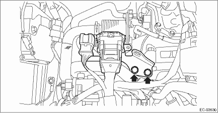
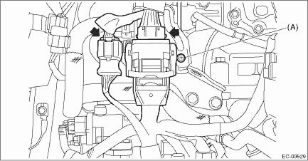
5. Connect the engine harness connector.
(1) Connect the bulkhead harness connector to the engine harness connector (black) and engine harness connector (brown).
(2) Install the bolt (A) which secures the bulkhead harness connector bracket.
Tightening torque:
7.5 N·m (0.8 kgf-m, 5.5 ft-lb)
6. Secure the air breather hose to the engine rear hanger using clip. (MT model)
7. Install the air intake boot. Air Intake Boot > INSTALLATION">
8. Install the center exhaust pipe. Center Exhaust Pipe > INSTALLATION">
9. Lower the vehicle.
10. Connect the battery ground terminal. NOTE">
11. Fill engine coolant. Engine Coolant > REPLACEMENT">
 Removal
EMISSION CONTROL (AUX. EMISSION CONTROL DEVICES)(H4DO) > EGR CoolerREMOVAL1. Disconnect the ground cable from battery.2. Drain engine coolant. Engine Coolant > REPLACEMENT">3. Remove th ...
 Egr pipe
...
Other materials:
Specification
VEHICLE DYNAMICS CONTROL (VDC) > General DescriptionSPECIFICATIONItemSpecification or identificationABS wheel speed sensorABS wheel speed sensor gap (for reference)Front0.77 — 1.43 mm (0.030 — 0.056 in)Rear0.44 — 1.76 mm (0.017 — 0.069 in)Identifications of harness (symbol)FrontRHZ1LHZ2Re ...
Component
ENTERTAINMENT > General DescriptionCOMPONENT1. DATA COMMUNICATION MODULE(1)Cap screw(4)Backup batteryTightening torque: N·m (kgf-m, ft-lb)(2)Backup battery cover(5)Data communication moduleT:0.3 (0.03, 0.2)(3)Circlip ...
Dtc b1620 side airbag sensor rh failure
AIRBAG SYSTEM (DIAGNOSTICS) > Diagnostic Chart with Trouble CodeDTC B1620 SIDE AIRBAG SENSOR RH FAILUREDIAGNOSIS START CONDITION:Ignition voltage is 10 V to 16 V.DTC DETECTING CONDITION:Side airbag sensor (RH) is faulty.When DTC B1620 is displayed, the circuit within the side airbag sensor (RH) i ...
