Subaru Crosstrek Service Manual: Inspection
WIPER AND WASHER SYSTEMS > Combination Switch (Wiper)
INSPECTION
1. INSPECTION OF SWITCH UNIT
1. Operate the switches to check the continuity between terminals.
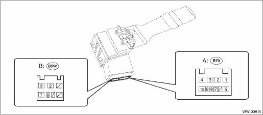
Switch position | Terminal No. | Standard | |
Front | OFF | A1 and A3 | Less than 1 ? |
INT | A1 and A3 | Less than 1 ? | |
LO | A2 and A3 | Less than 1 ? | |
HI | A2 and A4 | Less than 1 ? | |
Washer ON | B2 and B3 | Less than 1 ? | |
Rear | OFF | A5 and B2 B6 and B2 B7 and B2 | 1 M? or more |
LO | B6 and B2 | Less than 1 ? | |
HI | B7 and B2 | Less than 1 ? | |
Washer ON | A5 and B2 | Less than 1 ? |
2. Replace the switch if the inspection result is not within the standard.
2. FRONT WIPER
1. Check with Subaru Select Monitor
NOTE:
For detailed operation procedures, refer to “Application help”.
(1) Check the input signal when the switch assembly - combination wiper select is turned to LO or HI, using the «Data monitor» display.
(2) Does the input signal change corresponding to the switch operation?
• Yes > Finish the diagnosis.
• No > Check the harness.
2. Check the intermittent operation (inspection of the wiper switch alone)
(1) Set the voltmeter between terminals No. A2 (+) and No. B2 (−).
(2) Connect the battery to connector. (Terminal No. A2 (+), terminal No. B2 & A3 (−))
(3) Turn the switch assembly - combination wiper select to INT.
(4) Connect the battery (+) to the terminal No. A2 for 5 seconds.
(5) Connect the battery (−) to the terminal No. B2, and check the voltage between terminals No. A2 and No. A3 during intermittent operation.
(6) Perform step (1) to (5) above when intermittent control switch is in MIN or MAX, and replace the switch if the operation is not as specified.
Intermittent stationary time
MIN: Approx. 2 seconds
MAX: Approx. 16 seconds
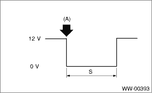
(A): | Connect the battery (−) to the terminal No. B2. |
S: | Intermittent downtime (sec.) |
3. REAR WIPER
1. Check input of body integrated unit
Check the input signal when the rear wiper switch is operated using Subaru Select Monitor.
NOTE:
For detailed operation procedures, refer to “Application help”.
(1) Turn the ignition switch to ON.
(2) Operate the rear wiper switch to each position of ON, INT and Washer ON.
(3) Does the input signal change corresponding to the switch operation?
• Yes > Go to step 4.
• No > Go to step 2.
2. Check harness
(1) Turn the ignition switch to OFF, disconnect the ground cable from battery. NOTE">
(2) Disconnect the connector of body integrated unit and wiper switch.
(3) Measure the resistance between body integrated unit and wiper switch.
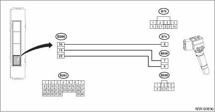
Connector & terminal
(B280) No. 30 — (B70) No. 5:
(B280) No. 22 — (B558) No. 6:
(B280) No. 12 — (B558) No. 7:
(4) Is the resistance less than 10 ??
• Yes > Go to step 3.
• No > Repair the harness between the body integrated unit and wiper switch.
3. Check input voltage of body integrated unit
(1) Connect the ground cable to battery.
(2) Turn the ignition switch to ON and check the input voltage of body integrated unit.
Connector & terminal
(i84) No. 6 (+) — Chassis ground (−):
(B281) No. 3 (+) — Chassis ground (−):
(3) Is the voltage 10 V or more?
• Yes > Go to step 4.
• No > Check the harness and fuse.
4. Check output of body integrated unit
Check the output signal when the rear wiper switch is operated using Subaru Select Monitor.
(1) Turn the ignition switch to ON.
(2) Operate the rear wiper switch to ON and Washer ON.
(3) When the operation in step (2) is performed, check the output signal of body integrated unit to rear wiper motor.
(4) When the rear wiper switch is set to ON, is ON output continuous? Also, when the washer is set to ON, is ON output?
• Yes > Go to step 5.
• No > Replace the body integrated unit. Body Integrated Unit">
5. Check output of body integrated unit
Check the output signal when the rear wiper switch is operated using Subaru Select Monitor.
(1) Turn the ignition switch to ON.
(2) Set the rear wiper switch to INT.
(3) When the operation in step (2) is performed, check the output signal of body integrated unit.
(4) When the rear wiper switch is set to INT, is ON/OFF output repeated? (INT OFF time (when vehicle parked): 12 seconds)
• Yes > Go to step 8.
• No > Go to step 6.
6. Check harness between body integrated unit and rear wiper motor
(1) Turn the ignition switch to OFF, disconnect the ground cable from battery. NOTE">
(2) Disconnect the connector of body integrated unit and wiper switch.
(3) Measure the resistance between the harness connector terminals of the body integrated unit and rear wiper motor.
Connector & terminal
(B280) No. 6 — (B97) No. 11:
(4) Is the resistance less than 10 ??
• Yes > Go to step 7.
• No > Repair the open circuit of the harness between body integrated unit and rear wiper motor.
7. Check stop position circuit of the rear wiper motor
(1) Disconnect the harness connector of the motor assembly - rear wiper.
(2) Check the continuity of the circuit of rear wiper motor stop position.
Connector & terminal
(D43) No. 1 (+) — (D43) No. 4 (−):
(3) Is there continuity between terminals?
• Yes > Go to step 8.
• No > Replace the motor assembly - rear wiper.
8. Check power supply circuit of the rear wiper motor
(1) Disconnect the harness connector of the motor assembly - rear wiper.
(2) Turn the ignition switch to ON.
(3) Measure the voltage between the rear wiper motor harness connector terminal and chassis ground.
Connector & terminal
(D43) No. 3 (+) — Chassis ground (−):
(4) Is the voltage 10 V or more?
• Yes > Go to step 9.
• No > Check the fuse (No. 27 in main fuse box).
9. Check ground circuit of rear wiper motor
(1) Turn the ignition switch to OFF.
(2) Measure the resistance between the rear wiper motor harness connector terminal and chassis ground.
Connector & terminal
(D43) No. 4 — Chassis ground:
(3) Is the resistance less than 10 ??
• Yes > Go to step 10.
• No > Repair the open circuit of the rear wiper motor ground circuit.
10. Check harness between body integrated unit and rear wiper motor
(1) Turn the ignition switch to OFF.
(2) Disconnect the harness connector of body integrated unit.
(3) Disconnect the harness connector of the motor assembly - rear wiper.
(4) Measure the resistance between the harness connector terminals of the body integrated unit and rear wiper motor.
Connector & terminal
(B280) No. 7 — (D43) No. 2:
(5) Is the resistance less than 10 ??
• Yes > Go to step 11.
• No > Repair the open circuit of the harness between body integrated unit and rear wiper motor.
11. Check output of body integrated unit
(1) Connect the harness connector of body integrated unit.
(2) Disconnect the connector of the motor assembly - rear wiper.
(3) Turn the ignition switch to ON.
(4) Measure the voltage between rear wiper motor connector and chassis ground.
Connector & terminal
(D43) No. 2 (+) — Chassis ground (−):
(5) Is the voltage less than 1.5 V when the rear wiper switch is OFF, and is the voltage 10 V or more when the rear wiper switch is ON?
• Yes > Go to step 12.
• No > Replace the body integrated unit. Body Integrated Unit">
12. Check operation of rear wiper motor
(1) Remove the motor assembly - rear wiper.
(2) Check the rear wiper motor. Rear Wiper Motor > INSPECTION">
(3) Does the rear wiper motor rotate normally?
• Yes > Finished.
• No > Replace the motor assembly - rear wiper.
NOTE:
Rear wiper intermittent time
Select lever position | Vehicle speed (km/h (MPH)) | Intermittent stopping time (sec.) |
Rev. | — | Continuous operation |
Except for reverse mode | 80 — (50 — ) | 3 |
50 — 80 (31 — 50) | 6 | |
20 — 50 (12 — 31) | 9 | |
0 — 20 (0 — 12) | 12 |

 Removal
WIPER AND WASHER SYSTEMS > Combination Switch (Wiper)REMOVAL1. Disconnect the ground cable from battery. NOTE">2. Remove the cover assembly - column.(1) Release the clips, and remove the c ...
Other materials:
Note
LIGHTING SYSTEM > Stop Light SystemNOTEFor operation procedures of each component of the stop light system, refer to the respective section.• Rear combination light assembly: Rear Combination Light Assembly">• Tail light/stop light bulb: Tail/Stop Light Bulb">• ...
Dtc u0101 lost communication with tcm
KEYLESS ACCESS WITH PUSH BUTTON START SYSTEM (DIAGNOSTICS) > Diagnostic Procedure with Diagnostic Trouble Code (DTC)DTC U0101 LOST COMMUNICATION WITH TCMDetected when CAN data from TCM does not arrive.NOTE:Perform the diagnosis for LAN system. Basic Diagnostic Procedure > PROCEDURE"> ...
Procedure
DIFFERENTIALS > Rear Differential Inspection ModePROCEDURECAUTION:Do not turn the power of the Subaru Select Monitor OFF during work, and do not disconnect the data link connector.1. Shift the select lever to “P” range.2. Apply the parking brake.3. Lift up the vehicle.WARNING:Lift up ...
