Subaru Crosstrek Service Manual: Inspection
TIRE PRESSURE MONITORING SYSTEM (DIAGNOSTICS) > Subaru Select Monitor
INSPECTION
1. COMMUNICATION FOR INITIALIZING IMPOSSIBLE
Detecting condition:
Defective harness connector
Trouble symptom:
Communication is impossible between the TPMS & keyless entry CM or TPMS CM and the Subaru Select Monitor.
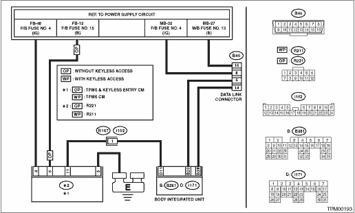
WIRING DIAGRAM:
Tire Pressure Monitoring System Tire Pressure Monitoring System > WIRING DIAGRAM">
| STEP | CHECK | YES | NO |
1.CHECK IGNITION SWITCH.
Is the ignition switch ON?
Subaru Select Monitor > INSPECTION">Go to Step 2.
Turn the ignition switch to ON, and select TPM mode using Subaru Select Monitor.
2.CHECK BATTERY.
Check the battery voltage. Battery">
Is the voltage 11 V or more?
Subaru Select Monitor > INSPECTION">Go to Step 3.
Charge or replace the battery.
3.CHECK BATTERY TERMINAL.
Check the battery terminal. Battery">
Is there poor contact at battery terminal?
Replace or tighten the battery terminal.
Subaru Select Monitor > INSPECTION">Go to Step 4.
4.CHECK SUBARU SELECT MONITOR COMMUNICATION.
1) Turn the ignition switch to ON.
2) Using the Subaru Select Monitor, check whether communication to other systems can be executed normally.
Is the system name displayed on Subaru Select Monitor?
Subaru Select Monitor > INSPECTION">Go to Step 8.
Subaru Select Monitor > INSPECTION">Go to Step 5.
5.CHECK SUBARU SELECT MONITOR COMMUNICATION.
1) Turn the ignition switch to OFF.
2) Disconnect the TPMS & keyless entry CM connector or TPMS CM connector.
3) Turn the ignition switch to ON.
4) Check whether communication to other systems can be executed normally.
Is the system name displayed on Subaru Select Monitor?
Replace the TPMS & keyless entry CM or TPMS CM. Tire Pressure Monitoring System">
Subaru Select Monitor > INSPECTION">Go to Step 6.
6.CHECK HARNESS CONNECTOR BETWEEN EACH CONTROL MODULE AND BODY INTEGRATED UNIT.
1) Turn the ignition switch to OFF.
2) Disconnect the connector of the TPMS & keyless entry CM or TPMS CM.
3) Measure the resistance between the body integrated unit and chassis ground.
Connector & terminal
(B40) No. 6 — Chassis ground:
(B40) No. 14 — Chassis ground:
Is the resistance 1 M? or more?
Subaru Select Monitor > INSPECTION">Go to Step 7.
Repair the harness and connector between each control module and body integrated unit.
7.CHECK OUTPUT SIGNAL TO TPMS & KEYLESS ENTRY CM OR TPMS CM.
1) Turn the ignition switch to ON.
2) Measure the voltage between TPMS & keyless entry CM or TPMS CM and chassis ground.
Connector & terminal
(B40) No. 6 (+) — Chassis ground (−):
(B40) No. 14 (+) — Chassis ground (−):
Is the voltage less than 1 V?
Subaru Select Monitor > INSPECTION">Go to Step 8.
Repair the harness and connector between each control module and body integrated unit.
8.CHECK HARNESS CONNECTOR BETWEEN TPMS & KEYLESS ENTRY CM OR TPMS CM AND BODY INTEGRATED UNIT.
1) Turn the ignition switch to OFF.
2) Measure the resistance between TPMS & keyless entry CM connector or TPMS CM connector and body integrated unit.
Connector & terminal
Without keyless access with push button start
(R221) No. 11 — (i171) No. 11:
With keyless access with push button start
(R211) No. 11 — (i171) No. 11:
Is the resistance less than 0.5 ??
Subaru Select Monitor > INSPECTION">Go to Step 9.
Repair the harness and connector between TPMS & keyless entry CM or TPMS CM and body integrated unit.
9.CHECK TPMS & KEYLESS ENTRY CM CONNECTOR OR TPMS CM CONNECTOR.
Is the connector inserted into the TPMS & keyless entry CM or TPMS CM until it locks?
Subaru Select Monitor > INSPECTION">Go to Step 10.
Insert the connector into the TPMS & keyless entry CM or TPMS CM.
10.CHECK POWER SUPPLY CIRCUIT.
1) Turn the ignition switch to ON.
2) Measure the ignition power supply voltage between TPMS & keyless entry CM connector or TPMS CM connector and chassis ground.
Connector & terminal
Without keyless access with push button start
(R221) No. 4 (+) — Chassis ground (−):
With keyless access with push button start
(R211) No. 4 (+) — Chassis ground (−):
Is the voltage 10 — 15 V?
Subaru Select Monitor > INSPECTION">Go to Step 11.
Repair open circuit of the harness between TPMS & keyless entry CM or TPMS CM and battery.
11.CHECK HARNESS CONNECTOR BETWEEN TPMS & KEYLESS ENTRY CM OR TPMS CM AND CHASSIS GROUND.
1) Turn the ignition switch to OFF.
2) Disconnect the connector from the TPMS & keyless entry CM or TPMS CM.
3) Measure the resistance of harness between TPMS & keyless entry CM or TPMS CM and chassis ground.
Connector & terminal
Without keyless access with push button start
(R221) No. 5 — Chassis ground:
With keyless access with push button start
(R211) No. 5 — Chassis ground:
Is the resistance less than 0.5 ??
Subaru Select Monitor > INSPECTION">Go to Step 12.
Repair open circuit of the harness of TPMS & keyless entry CM or TPMS CM.
12.CHECK POOR CONTACT OF CONNECTOR.
Is there poor contact in TPMS & keyless entry CM power supply or TPMS CM power supply, ground line and body integrated unit?
Repair the connector.
Replace the TPMS & keyless entry CM or TPMS CM. Tire Pressure Monitoring System">

 Operation
TIRE PRESSURE MONITORING SYSTEM (DIAGNOSTICS) > Subaru Select MonitorOPERATIONFor detailed operation procedures, refer to “Application help”.NOTE:If TPMS & keyless entry CM or TPMS ...
Other materials:
Inspection
CONTINUOUSLY VARIABLE TRANSMISSION(TR580) > Reverse Brake AssemblyINSPECTION• Inspect the drive plate facing for wear and damage.• Check the driven plate for discoloration (burnt color).• Check for worn snap ring, fatigue or damaged return spring or deformed spring retainer.&bul ...
Electrical specification
POWER ASSISTED SYSTEM (POWER STEERING) (DIAGNOSTICS) > Control Module I/O SignalELECTRICAL SPECIFICATIONNOTE:The terminal numbers of the power steering control module connectors are as indicated in the figure.ContentsTerminal No.Input/output signalMeasured value and measuring conditionsPower supp ...
Assembly
COOLING(H4DO) > Radiator Main Fan and Fan MotorASSEMBLYAssemble in the reverse order of disassembly.Tightening torque:4.41 N·m (0.45 kgf-m, 3.25 ft-lb)Tightening torque:3.4 N·m (0.3 kgf-m, 2.5 ft-lb) ...
