Subaru Crosstrek Service Manual: Inspection
LIGHTING SYSTEM > Room Light
INSPECTION
1. ROOM LIGHT BULB
1. Visually check the bulb for blow out.
2. Check the bulb specification. General Description > SPECIFICATION">
3. Replace the bulb if it is found defective.
2. ROOM LIGHT SWITCH
1. Check the resistance between switch terminals.
Preparation tool:
Circuit tester
Terminal No. | Inspection conditions | Standard | Connection diagram |
1 — 3 | Switch OFF | 1 M? or more |
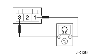
Switch ON
Less than 1 ?
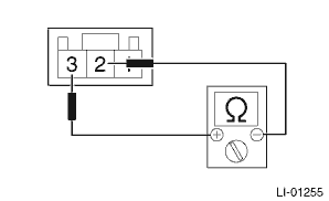
2 — 3
Switch door
Less than 1 ?
2. Apply battery voltage to check the lighting condition of the light.
Terminal No. | Inspection conditions | Specification | Connection diagram |
3 (+) — 1, 2 (−) | Switch OFF | Light OFF |
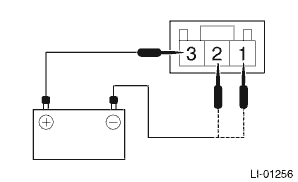
Switch ON
Light ON
Switch door
Light ON
3. Replace the light assembly - room if the inspection result is not within the standard value.
 Room light
...
 Removal
LIGHTING SYSTEM > Room LightREMOVAL1. Disconnect the ground cable from battery. NOTE">2. Remove the light assembly - room.CAUTION:When using a flat tip screwdriver, apply protective tape o ...
Other materials:
Installation
CLUTCH SYSTEM > Clutch PedalINSTALLATION1. Install in the reverse order of removal.CAUTION:Always use a new clevis pin.Tightening torque:Clutch pedal18 N·m (1.8 kgf-m, 13.3 ft-lb)Knee airbag module7.5 N·m (0.76 kgf-m, 5.5 ft-lb)Air intake boot3 N·m (0.3 kgf-m, 2.2 ft-lb)2. Ad ...
Removal
CONTINUOUSLY VARIABLE TRANSMISSION(TR580) > Air Breather HoseREMOVAL1. FRONT DIFFERENTIAL SIDE1. Remove the clip (A) from the air intake boot.2. Loosen the clamp (B) connecting the air intake boot and air cleaner case (rear).3. Loosen the clamp (C) which connects the air intake boot and throttle ...
Inspection
CONTINUOUSLY VARIABLE TRANSMISSION(TR580) > Primary Speed SensorINSPECTION1. Set the ST between the TCM and bulkhead harness.ST 18460AA040CHECK BOARD2. Set the probe of oscilloscope to the check board connector.Connector & terminalNo. 14 (+) — No. 42 (−):(A)+ probe(B)− probe3 ...
