Subaru Crosstrek Service Manual: Inspection
HVAC SYSTEM (HEATER, VENTILATOR AND A/C) > In-Vehicle Sensor (Auto A/C Model)
INSPECTION
1. Set the vehicle to the following conditions.
Item | Condition |
Ignition switch | ON |
A/C switch | ON |
Temperature adjustment dial | HI (MAX HOT) |
Air flow control dial or switch | DEF |
Fan dial | HI (MAX) |
2. Check the suction port (A) for in-vehicle sensor of the cover assembly - instrument panel LWR driver INN.
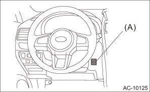
(1) Put a strip of paper close to the front side of the suction port (A).
(2) Can you see the paper moving towards the port and the air being sucked into the port?
CAUTION:
Be careful not to let the paper get sucked into the port.
• Yes > Go to step 5).
• No > Go to step 3).
3. Remove the cover assembly - instrument panel LWR driver INN, and check the aspirator hose (A).
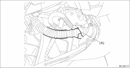
(1) Are the aspirator hoses on both sides of the case and sensor connected securely?
(2) Is the aspirator hose free from any kinks or cracks?
• Yes > Go to step 4).
• No > Repair or replace the aspirator hose if necessary.
4. Check if there is anything that affects sensing, around the in-vehicle sensor.
(1) Is the in-vehicle sensor hole free from clogging?
(2) Is the peripheral area of in-vehicle sensor free from any heat-producing parts (such as audio, navigation system etc.)?
• Yes > Go to step 5).
• No > Remove everything that affects sensing.
5. Perform the inspection of in-vehicle sensor unit.
(1) Disconnect the in-vehicle sensor connector.
(2) Is the resistance between terminals of in-vehicle sensor within standard value?
CAUTION:
During inspection, be careful not to touch the sensor end in order to avoid misjudgment due to body temperature.
Preparation tool:
Circuit tester
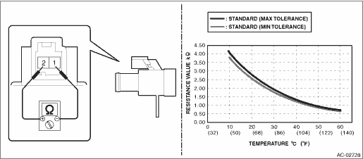
Terminal No. | Inspection conditions | Standard |
1 — 2 | 10°C | 3.772 — 4.101 k? |
15°C | 3.096 — 3.338 k? | |
20°C | 2.556 — 2.734 k? | |
25°C | 2.121 — 2.251 k? | |
30°C | 1.756 — 1.878 k? | |
35°C | 1.462 — 1.574 k? | |
40°C | 1.223 — 1.326 k? | |
45°C | 1.028 — 1.122 k? | |
50°C | 0.868 — 0.9542 k? | |
55°C | 0.7363 — 0.8147 k? | |
60°C | 0.6273 — 0.6984 k? |
• Yes > The in-vehicle sensor is normal.
• No > Replace the in-vehicle sensor.

 Removal
HVAC SYSTEM (HEATER, VENTILATOR AND A/C) > In-Vehicle Sensor (Auto A/C Model)REMOVALCAUTION:Be careful not to damage the sensors and interior trims when removing.1. Disconnect the battery ground ca ...
Other materials:
Preparation for screen settings
1. Turn the ignition switch to the "ON"
position.
2. Push and hold the
button to show
the selection screen.
3. After the selection screen is displayed,
operate the "
" or "
" switch to show the
"Screen Setting" item. Then, push the
button. ...
SRS airbag (Supplemental Restraint System airbag)
*SRS: This stands for supplemental restraint
system. This name is used because
the airbag system supplements the
vehicle's seatbelts.
Your vehicle is equipped with a supplemental
restraint system in addition to a
lap/shoulder belt at each front seating
position and each rear window-side sea ...
Wiring diagram
POWER ASSISTED SYSTEM (POWER STEERING) (DIAGNOSTICS) > Control Module I/O SignalWIRING DIAGRAM(1)Battery(5)Engine control module (ECM)(9)Torque sensor (main & sub)(2)Ignition switch(6)Power steering control module(10)CAN communication(3)STEERING warning light (combination meter)(7)Motor(11)VD ...
