Subaru Crosstrek Service Manual: Inspection
GLASS/WINDOWS/MIRRORS > Rear Window Defogger System
INSPECTION
1. CHECK SYSTEM
Symptoms | Inspection order |
Rear window defogger does not operate. |
(1) Check the fuse.
(2) Check the rear defogger relay.
(3) Check the rear window defogger switch.
(4) Check the heat wire.
(5) Check the wiring harness.
(6) Check body integrated unit.
NOTE:
Rear window defogger system can be customized using the Subaru Select Monitor, when the customize setting {Auto A/C Setting} of the body integrated unit is set to {support}.
System name | Initial setting | Customize setting |
Rear defogger operation mode | Normal | Continuous |
2. CHECK WITH SUBARU SELECT MONITOR
CAUTION:
Before performing inspection, check whether the rear defogger operation mode setting is either in initial setting or customize setting.
1. Check the input signal when the rear window defogger switch is operated using Subaru Select Monitor.
(1) Connect the Subaru Select Monitor to data link connector.
NOTE:
For detailed operation procedures, refer to “Application help”.
(2) Turn the ignition switch to ON.
(3) On «Start» display, select «Diagnosis».
(4) On «Vehicle selection» display, input the target vehicle information and select «Confirmed».
(5) On «Main Menu» display, select «Each System».
(6) On «Select System» display, select «Body Control» and then select «Enter».
(7) On «Select Function» display, select «Data Monitor».
(8) From the data monitor item list, select «Auto A/C Setting».
(9) Check the vehicle equipment and the settings of body integrated unit.
If correct, go to (10).
If not correct, go to (13).
(10) From the data monitor item list, select «Rr Defogger output».
(11) Check the displayed data (ON/OFF) by operating the rear window defogger switch.
(12) On «Select Function» display, select «Customize».
(13) From the Customize item list, select «Auto A/C Setting» and match the auto A/C ECM setting to the actual vehicle equipment.
2. Check the operation with rear window defogger switch ON.
• When customize setting is set as “Continuous”, it is normal if the 15-minute operation and 2-minute stop repeats.
• When customize setting is “Normal”, it is normal if the operation lasts for 15 minutes and then turns OFF.
3. When the operation in 2) above fails, replace the body integrated unit.
3. HEAT WIRE INSPECTION
CAUTION:
Use a dry soft cloth to wipe off dirt on the glass along the heat wires with care not to damage the heat wires.
1. Prepare the following checking items.
• Liquid crystal thermograph sheet (approximate Size: 300 ? 300 mm (11.8 ? 11.8 in) and thermal temperature: 35 — 40°C (95 — 104°F))
• Aluminum foil
2. Turn the ignition switch to ON.
3. Turn the defogger switch to ON.
4. Push the liquid crystal thermograph sheet from the outside of the glass - rear window.
NOTE:
Use the liquid crystal thermograph sheet every range it is separated with the separate line.
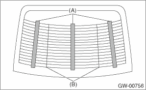
(A) | Liquid crystal thermograph sheet |
(B) | Separate line |
5. Determine the faulty heat wire by checking the color of the liquid crystal thermograph sheet.
Liquid crystal thermograph sheet | Criteria |
Change occurred (red > blue) | Normal |
No change (black) | Open |
NOTE:
• Check from the inside of the glass - rear window if the liquid crystal thermograph sheet does not change.
• The time for the color change may differ depends on the surface temperature of the glass.
6. Wrap a piece of aluminum foil around the tip of tester probe and press it against the heat wire with your finger.
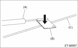
(A) | Tester probe |
(B) | Aluminum foil |
(C) | Heat wire |
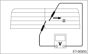
7. To both ends of the section that has been found to include an open in the step 5), apply the tester positive (+) probe and the negative (−) probe.
8. Move the tester probe on the negative (−) side slowly along the heat wire. If voltage changes from zero while moving the tester probe, heat wire is open at the voltage change point.
9. Repair the heat wire that determines the place of the open circuit. Rear Window Defogger System > REPAIR">

 Wiring diagram
GLASS/WINDOWS/MIRRORS > Rear Window Defogger SystemWIRING DIAGRAMRefer to “Rear Defogger System” in the wiring diagram. Rear Defogger System > WIRING DIAGRAM"> ...
Other materials:
Bypass screen setting
1. Perform the preparation steps according
to "Preparation for screen settings"
2. Operate the "
" or "
" switch to
select the "Bypass Screen" item. Then
push the
button.
3. Select the item to set by operating the
"
" or "
" switches. Then push the
button ...
Electrical component location Location
OCCUPANT DETECTION SYSTEM (DIAGNOSTICS) > Electrical Component LocationLOCATION(1)Occupant detection control module(3)Airbag ON/OFF indicator light(4)Buckle switch (passenger’s seat)(2)Occupant detection sensor ...
Dtc b1613 front sub sensor rh initialization error
AIRBAG SYSTEM (DIAGNOSTICS) > Diagnostic Chart with Trouble CodeDTC B1613 FRONT SUB SENSOR RH INITIALIZATION ERRORDiagnosis start condition:Ignition voltage is 10 V to 16 V.DTC detecting condition:• Open or short circuit in harness of front sensor bus (RH)• Front sub sensor (RH) is fa ...
