Subaru Crosstrek Service Manual: Inspection
CLUTCH SYSTEM > Clutch Switch
INSPECTION
1. CLUTCH START SWITCH
1. Perform the following inspections. If the clutch start switch does not operate normally, adjust the switch, and check it again. Clutch Switch > ADJUSTMENT">
• Make sure that engine does not start with clutch pedal not depressed.
• Make sure that engine starts with clutch pedal fully depressed.
2. When the clutch start switch does not operate normally even if it is adjusted, check the clutch start switch for continuity.
(1) Remove the clutch start switch. Clutch Switch > REMOVAL">
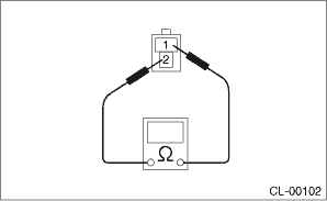
(2) Measure the resistance between terminal 1 and 2 of the switch. If the resistance is not at the standard value, replace the switch.
Condition | Terminal No. | Specified resistance |
ON | No. 1 — No. 2 | Less than 1 ? |
OFF | No. 1 — No. 2 | 1 M? or more |
(3) Check that the switch is turned on and off in dimension L.
Dimension L:
9 — 10 mm (0.35 — 0.39 in)
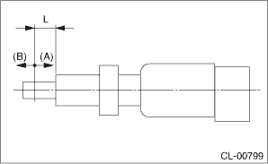
(A) | ON |
(B) | OFF |
(4) Install the clutch start switch. Clutch Switch > INSTALLATION">
2. CLUTCH SWITCH
1. Check the clutch switch for continuity.
(1) Disconnect the connector of clutch switch.
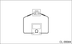
(2) Measure the resistance between terminal 1 and 2 of the switch. If the resistance is not within the specification, check the clutch stroke and installation condition, and check the clutch switch again.
Condition | Terminal No. | Specified resistance |
When clutch pedal is depressed | No. 1 — No. 2 | 1 M? or more |
When the clutch pedal is not depressed | No. 1 — No. 2 | Less than 1 ? |
2. When the clutch switch does not operate normally even if the clutch stroke and installation condition are normal, check the clutch switch for continuity.
(1) Remove the clutch switches. Clutch Switch > REMOVAL">
(2) Measure the resistance between terminal 1 and 2 of the switch. If the resistance is not at the standard value, replace the switch.
Condition | Terminal No. | Specified resistance |
ON | No. 1 — No. 2 | Less than 1 ? |
OFF | No. 1 — No. 2 | 1 M? or more |
(3) Check that the switch is turned on and off in dimension L.
Dimension L:
5 — 6.5 mm (0.2 — 0.26 in)
(A) | ON |
(B) | OFF |
(4) Install the clutch switch. Clutch Switch > INSTALLATION">
 Removal
CLUTCH SYSTEM > Clutch SwitchREMOVALCAUTION:Before handling the airbag system components, refer to “CAUTION” of “General Description” in “AIRBAG SYSTEM”. Genera ...
 Installation
CLUTCH SYSTEM > Clutch SwitchINSTALLATION1. CLUTCH SWITCH1. Install the clutch switch.2. Move the clevis pin of push rod to left and right, retain it at the position where it moves smoothly, and me ...
Other materials:
Assembly
BRAKE > Front Disc Brake AssemblyASSEMBLY1. Before assembly, check each part. Front Disc Brake Assembly > INSPECTION">2. Clean the inside of the caliper body cylinder using brake fluid.3. Apply a coat of brake fluid to piston seal and install the piston seal to the caliper body cylind ...
Charge
STARTING/CHARGING SYSTEMS(H4DO) > BatteryCHARGEWARNING:• Do not bring an open flame close to the battery when working.CAUTION:• Prior to charging, corroded terminals should be cleaned with a brush and common caustic soda solution.• Be careful while charging the battery because i ...
Rear seatbelts (except rear center seatbelt)
1. Sit well back in the seat.
2. Pick up the tongue plate and pull the
belt out slowly. Do not let it get twisted.
If the belt stops before reaching the
buckle, return the belt slightly and pull
it out more slowly.
If the belt still cannot be unlocked,
let the belt retract slightly a ...
