Subaru Crosstrek Service Manual: Fuel pump circuit
ENGINE (DIAGNOSTICS)(H4DO) > Diagnostics for Engine Starting Failure
FUEL PUMP CIRCUIT
CAUTION:
After servicing or replacing faulty parts, perform Clear Memory Mode Clear Memory Mode > OPERATION"> , and Inspection Mode Inspection Mode > PROCEDURE">.
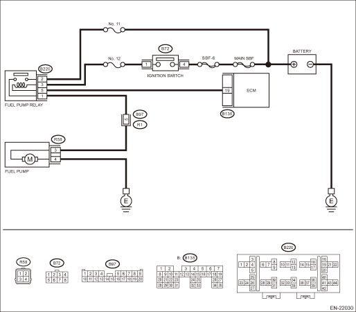
Wiring diagram:
Engine electrical system Engine Electrical System">
| STEP | CHECK | YES | NO |
1.CHECK OPERATING SOUND OF FUEL PUMP.
Check if the fuel pump operates for two seconds when turning the ignition switch to ON.
NOTE:
Fuel pump operation can be executed using the Subaru Select Monitor.
Refer to “Active Test” for the procedures. Active Test">
Does the fuel pump emit operating sound?
Check the fuel injector circuit. Diagnostics for Engine Starting Failure > FUEL INJECTOR CIRCUIT">
Diagnostics for Engine Starting Failure > FUEL PUMP CIRCUIT">Go to Step 2.
2.CHECK GROUND CIRCUIT OF FUEL PUMP.
1) Turn the ignition switch to OFF.
2) Remove the fuel pump access hole lid.
3) Disconnect the connector from fuel pump.
4) Measure the resistance of harness between fuel pump and chassis ground.
Connector & terminal
(R58) No. 4 — Chassis ground:
Is the resistance less than 5 ??
Diagnostics for Engine Starting Failure > FUEL PUMP CIRCUIT">Go to Step 3.
Repair the open circuit in harness between fuel pump connector and chassis ground terminal.
3.CHECK POWER SUPPLY TO FUEL PUMP.
1) Turn the ignition switch to ON.
2) Measure the voltage of power supply circuit between fuel pump connector and chassis ground.
Connector & terminal
(R58) No. 3 (+) — Chassis ground (−):
Is the voltage 10 V or more?
Replace the fuel pump. Fuel Pump">
Diagnostics for Engine Starting Failure > FUEL PUMP CIRCUIT">Go to Step 4.
4.CHECK HARNESS BETWEEN FUEL PUMP CONNECTOR AND FUEL PUMP RELAY CONNECTOR.
1) Turn the ignition switch to OFF.
2) Remove the fuel pump relay.
3) Measure the resistance of harness between fuel pump connector and fuel pump relay connector.
Connector & terminal
(R58) No. 3 — (B220) No. 1:
Is the resistance less than 1 ??
Diagnostics for Engine Starting Failure > FUEL PUMP CIRCUIT">Go to Step 5.
Repair the harness and connector.
NOTE:
In this case, repair the following item:
• Open circuit in harness between fuel pump connector and fuel pump relay connector
• Poor contact of coupling connector
5.CHECK HARNESS BETWEEN FUEL PUMP CONNECTOR AND FUEL PUMP RELAY CONNECTOR.
Measure the resistance between fuel pump connector and chassis ground.
Connector & terminal
(R58) No. 3 — Chassis ground:
Is the resistance 1 M? or more?
Diagnostics for Engine Starting Failure > FUEL PUMP CIRCUIT">Go to Step 6.
Repair the short circuit to ground in harness between fuel pump connector and fuel pump relay connector.
6.CHECK FUEL PUMP RELAY.
1) Connect the battery to fuel pump relay terminals No. 3 and No. 5.
2) Measure the resistance between fuel pump relay terminals.
Terminals
No. 1 — No. 2:
Is the resistance less than 1 ??
Diagnostics for Engine Starting Failure > FUEL PUMP CIRCUIT">Go to Step 7.
Replace the fuel pump relay. Fuel Pump Relay">
7.CHECK HARNESS BETWEEN ECM AND FUEL PUMP RELAY CONNECTOR.
1) Disconnect the connector from ECM.
2) Measure the resistance of harness between ECM connector and fuel pump relay connector.
Connector & terminal
(B135) No. 19 — (B220) No. 5:
Is the resistance less than 1 ??
Diagnostics for Engine Starting Failure > FUEL PUMP CIRCUIT">Go to Step 8.
Repair the open circuit of harness between ECM connector and fuel pump relay connector.
8.CHECK POWER SUPPLY OF FUEL PUMP RELAY.
1) Turn the ignition switch to ON.
2) Measure the voltage between fuel pump relay connector and chassis ground.
Connector & terminal
(B220) No. 2 (+) — Chassis ground (−):
(B220) No. 3 (+) — Chassis ground (−):
Is the voltage 10 V or more?
Repair the poor contact of ECM connector.
Repair the open or ground short in the harness of power supply circuit.
 Ignition control system
ENGINE (DIAGNOSTICS)(H4DO) > Diagnostics for Engine Starting FailureIGNITION CONTROL SYSTEMCAUTION:After servicing or replacing faulty parts, perform Clear Memory Mode Clear Memory Mode">, ...
 Fuel injector circuit
ENGINE (DIAGNOSTICS)(H4DO) > Diagnostics for Engine Starting FailureFUEL INJECTOR CIRCUITCAUTION:• Check or repair only faulty parts.• After servicing or replacing faulty parts, perform ...
Other materials:
Steering angle sensor Replacement
VEHICLE DYNAMICS CONTROL (VDC) > Steering Angle SensorREPLACEMENTCAUTION:• If the steering wheel and steering angle sensor are removed, perform the following VDC setting mode.– Model without EyeSight: VDC sensor midpoint setting mode VDC Control Module and Hydraulic Control Unit (VDCCM& ...
Dtc b28ac stereo camera asic
EyeSight (DIAGNOSTICS) > Diagnostic Procedure with Diagnostic Trouble Code (DTC)DTC B28AC STEREO CAMERA ASICDetected when communication error occurs due to malfunction of ASIC.DTC DETECTING CONDITION:Communication error occurs due to malfunction of ASIC.TROUBLE SYMPTOM:All functions of EyeSight s ...
Preparation tool
KEYLESS ACCESS WITH PUSH BUTTON START SYSTEM (DIAGNOSTICS) > General DescriptionPREPARATION TOOL1. SPECIAL TOOLILLUSTRATIONTOOL NUMBERDESCRIPTIONREMARKS — SUBARU SELECT MONITOR 4Used for setting of each function and troubleshooting for electrical system.NOTE:For detailed operation procedures of ...
