Subaru Crosstrek Service Manual: Fuel injector circuit
ENGINE (DIAGNOSTICS)(H4DO) > Diagnostics for Engine Starting Failure
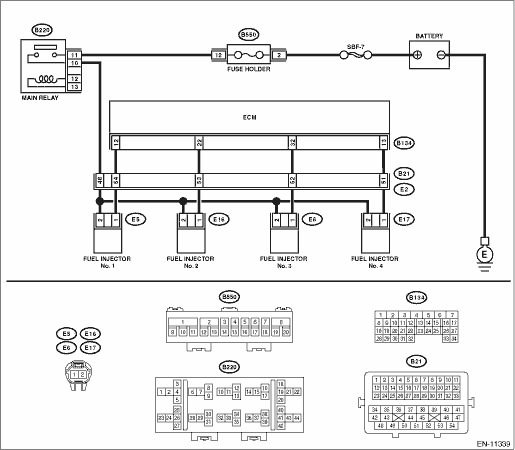
FUEL INJECTOR CIRCUIT
CAUTION:
• Check or repair only faulty parts.
• After servicing or replacing faulty parts, perform Clear Memory Mode Clear Memory Mode > OPERATION"> , and Inspection Mode Inspection Mode > PROCEDURE">.
WIRING DIAGRAM:
Engine electrical system Engine Electrical System">
| STEP | CHECK | YES | NO |
1.CHECK OPERATION OF EACH FUEL INJECTOR.
While cranking the engine, check each fuel injector emits operating sound. Use a sound scope or attach a screwdriver to the injector to listen to sounds for this check.
Does the fuel injector emit operating sound?
Check the fuel pressure. Fuel Pressure > INSPECTION">
Diagnostics for Engine Starting Failure > FUEL INJECTOR CIRCUIT">Go to Step 2.
2.CHECK POWER SUPPLY TO EACH FUEL INJECTOR.
1) Turn the ignition switch to OFF.
2) Disconnect the connector from fuel injector.
3) Turn the ignition switch to ON.
4) Measure the power supply voltage between fuel injector terminal and engine ground.
Connector & terminal
#1 (E5) No. 2 (+) — Engine ground (−):
#2 (E16) No. 2 (+) — Engine ground (−):
#3 (E6) No. 2 (+) — Engine ground (−):
#4 (E17) No. 2 (+) — Engine ground (−):
Is the voltage 10 V or more?
Diagnostics for Engine Starting Failure > FUEL INJECTOR CIRCUIT">Go to Step 3.
Repair the harness and connector.
NOTE:
In this case, repair the following item:
• Open circuit in harness between main relay connector and fuel injector connector
• Poor contact of main relay connector
• Poor contact of coupling connector
3.CHECK HARNESS BETWEEN ECM AND FUEL INJECTOR CONNECTOR.
1) Turn the ignition switch to OFF.
2) Disconnect the connector from ECM.
3) Measure the resistance of harness between ECM connector and fuel injector connector.
Connector & terminal
#1 (B134) No. 12 — (E5) No. 1:
#2 (B134) No. 22 — (E16) No. 1:
#3 (B134) No. 32 — (E6) No. 1:
#4 (B134) No. 13 — (E17) No. 1:
Is the resistance less than 1 ??
Diagnostics for Engine Starting Failure > FUEL INJECTOR CIRCUIT">Go to Step 4.
Repair the harness and connector.
NOTE:
In this case, repair the following item:
• Open circuit in harness between ECM connector and fuel injector connector
• Poor contact of coupling connector
4.CHECK HARNESS BETWEEN ECM AND FUEL INJECTOR CONNECTOR.
Measure the resistance between ECM connector and chassis ground.
Connector & terminal
#1 (B134) No. 12 — Chassis ground:
#2 (B134) No. 22 — Chassis ground:
#3 (B134) No. 32 — Chassis ground:
#4 (B134) No. 13 — Chassis ground:
Is the resistance 1 M? or more?
Diagnostics for Engine Starting Failure > FUEL INJECTOR CIRCUIT">Go to Step 5.
Repair the short circuit to ground in harness between ECM connector and fuel injector connector.
5.CHECK EACH FUEL INJECTOR.
Measure the resistance between each fuel injector terminals.
Terminals
No. 1 — No. 2:
Is the resistance 5 — 20 ??
Diagnostics for Engine Starting Failure > FUEL INJECTOR CIRCUIT">Go to Step 6.
Replace the faulty fuel injector. Fuel Injector">
6.CHECK FOR POOR CONTACT.
Check for poor contact of ECM connector.
Is there poor contact of ECM connector?
Repair the poor contact of ECM connector.
Inspection using “General Diagnostic Table” General Diagnostic Table > INSPECTION">
 Fuel pump circuit
ENGINE (DIAGNOSTICS)(H4DO) > Diagnostics for Engine Starting FailureFUEL PUMP CIRCUITCAUTION:After servicing or replacing faulty parts, perform Clear Memory Mode Clear Memory Mode > OPERATION&q ...

Other materials:
Remote engine start system Wiring diagram
WIRING SYSTEM > Remote Engine Start SystemWIRING DIAGRAM ...
Total trailer weight
Total trailer weight
The total trailer weight (trailer weight plus
its cargo load) must never exceed the
maximum total trailer weight in the following
table.
Conditions
Maximum total trailer weight
When towing a trailer without brakes.
1,000 lbs (453 kg)
When ...
Dtc b1828 short in side airbag lh (to +b)
AIRBAG SYSTEM (DIAGNOSTICS) > Diagnostic Chart with Trouble CodeDTC B1828 SHORT IN SIDE AIRBAG LH (TO +B)Diagnosis start condition:Ignition voltage is 10 V to 16 V.DTC detecting condition:• Side airbag harness (LH) is shorted to power supply.• Side airbag module (LH) is faulty.• ...
