Subaru Crosstrek Service Manual: Electrical specification
VEHICLE DYNAMICS CONTROL (VDC) (DIAGNOSTICS) > Control Module I/O Signal
ELECTRICAL SPECIFICATION
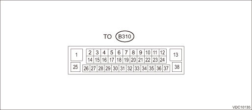
• Models without EyeSight
NOTE:
• Terminal numbers in VDCCM&H/U connector (on the control module side) are shown in the figure.
• When the connector is removed from the VDCCM&H/U, the brake warning light (EBD warning light), ABS warning light, VDC warning light & VDC indicator light, VDC OFF indicator light, and the hill start assist warning light illuminate.
Content | Terminal No. (+) — (−) | Input/Output signal | ||
Measured value and measuring conditions | ||||
Power supply | 28 — 38 | 10 — 15 V when the ignition switch is ON. | ||
ABS wheel speed sensor | Front LH wheel | Power supply | 19 — 38 | 0 — 18 V when the ignition switch is ON. |
Signal | 8 | 7 — 14 mA: Rectangle waveform | ||
Front RH wheel | Power supply | 16 — 38 | 0 — 18 V when the ignition switch is ON. | |
Signal | 4 | 7 — 14 mA: Rectangle waveform | ||
Rear LH wheel | Power supply | 31 — 38 | 0 — 18 V when the ignition switch is ON. | |
Signal | 18 | 7 — 14 mA: Rectangle waveform | ||
Rear RH wheel | Power supply | 17 — 38 | 0 — 18 V when the ignition switch is ON. | |
Signal | 29 | 7 — 14 mA: Rectangle waveform | ||
Valve relay power supply | 25 — 38 | 10 — 15 V | ||
Motor relay power supply | 1 — 13 | 10 — 15 V | ||
Stop light switch | 30 — 38 | 1.5 V or less when the stop light is OFF; 10 — 15 V when the stop light is ON. | ||
Vehicle speed output signal | 2 | 0 ←> 12 V pulse | ||
VDC OFF switch | 12 — 38 | 1 ? or less when the OFF switch is “ON”; 1 M? or more when the switch is “OFF”. | ||
CAN communication line (H) | 26 | Pulse signal | ||
CAN communication line (L) | 14 | Pulse signal | ||
Ground | 38 | — | ||
Ground | 13 | — | ||
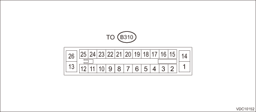
• Models with EyeSight
NOTE:
• Terminal numbers in VDCCM&H/U connector (on the control module side) are shown in the figure.
• When the connector is removed from the VDCCM&H/U, the brake warning light (EBD warning light), ABS warning light, VDC warning light & VDC indicator light, VDC OFF indicator light, and the hill start assist warning light illuminate.
Content | Terminal No. (+) — (−) | Input/Output signal | ||
Measured value and measuring conditions | ||||
Power supply | 20 — 26 | 10 — 15 V when the ignition switch is ON. | ||
ABS wheel speed sensor | Front LH wheel | Power supply | 9 — 26 | 0 — 18 V when the ignition switch is ON. |
Signal | 8 | 7 — 14 mA: Rectangle waveform | ||
Front RH wheel | Power supply | 5 — 26 | 0 — 18 V when the ignition switch is ON. | |
Signal | 6 | 7 — 14 mA: Rectangle waveform | ||
Rear LH wheel | Power supply | 3 — 26 | 0 — 18 V when the ignition switch is ON. | |
Signal | 2 | 7 — 14 mA: Rectangle waveform | ||
Rear RH wheel | Power supply | 11 — 26 | 0 — 18 V when the ignition switch is ON. | |
Signal | 12 | 7 — 14 mA: Rectangle waveform | ||
Valve relay power supply | 1 — 26 | 10 — 15 V | ||
Motor relay power supply | 14 — 26 | 10 — 15 V | ||
Stop light switch | 16 — 26 | 1.5 V or less when the stop light is OFF; 10 — 15 V when the stop light is ON. | ||
Subaru Select Monitor | 18 — 26 | 0 ←> 12 V pulse (during the communication) | ||
Vehicle speed output signal | 24 | 0 ←> 12 V pulse | ||
VDC OFF switch | 22 — 26 | 0.5 ? or less when the OFF switch is ON; 1 M? or more when the switch is OFF. | ||
CAN communication line (H) | 23 | Pulse signal | ||
CAN communication line (L) | 21 | Pulse signal | ||
Ground | 26 | — | ||

 Wiring diagram
VEHICLE DYNAMICS CONTROL (VDC) (DIAGNOSTICS) > Control Module I/O SignalWIRING DIAGRAMRefer to “Vehicle Dynamics Control System” in the wiring diagram. Vehicle Dynamics Control System& ...
Other materials:
Preparation tool
CRUISE CONTROL SYSTEM (DIAGNOSTICS) > General DescriptionPREPARATION TOOL1. SPECIAL TOOLILLUSTRATIONTOOL NUMBERDESCRIPTIONREMARKS — SUBARU SELECT MONITOR 4Used for setting of each function and troubleshooting for electrical system.NOTE:For detailed operation procedures of Subaru Select Monitor ...
General diagnostic table Inspection
TIRE PRESSURE MONITORING SYSTEM (DIAGNOSTICS) > General Diagnostic TableINSPECTIONSymptomsFaulty partsTire pressure warning light illuminates.Tire pressure is reduced.• Improper tire pressure adjustment• Punctured tireTire pressure warning light blinks 25 times and then illuminates.Ti ...
Except U.S.-spec. models (type B)
The illustration above is a typical example. For some models, the combination
meter
may be slightly different than that shown in the illustration.
Tachometer
Multi information display
Fuel gauge
Select lever/gear position indicator
Speedometer
Trip meter A/B selection and trip m ...
