Subaru Crosstrek Service Manual: Electrical specification
EyeSight (DIAGNOSTICS) > Control Module I/O Signal
ELECTRICAL SPECIFICATION
1. STEREO CAMERA
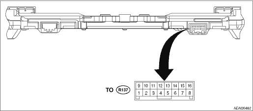
Terminal No. | Content | Measuring condition | Standard |
(R137) No. 1 | — | — | — |
(R137) No. 2 | — | — | — |
(R137) No. 3 | — | — | — |
(R137) No. 4 | — | — | — |
(R137) No. 5 | — | — | — |
(R137) No. 6 ←> Chassis ground | Ignition power supply | Ignition switch OFF > ON | Less than 1 V > 9 — 16 V |
(R137) No. 7 ←> Chassis ground | GND | Always | Less than 1 ? |
(R137) No. 8 ←> Chassis ground | Battery power supply | Always | 9 — 16 V |
(R137) No. 9 ←> Chassis ground | CAN L | Always | 1 k? or more |
(R137) No. 10 ←> Chassis ground | CAN H | Always | 1 k? or more |
(R137) No. 11 | — | — | — |
(R137) No. 12 ←> Chassis ground | Pre-collision brake OFF switch input | Pre-collision brake OFF switch OFF > ON | Approx. 1 k? > less than 1 ? |
(R137) No. 13 ←> Chassis ground | Lane departure warning OFF switch input | Lane departure warning OFF switch OFF > ON | Approx. 1 k? > less than 1 ? |
(R137) No. 14 ←> (R137) No. 15 | EyeSight steering switch input | ALL OFF (no switch operation) | 3.6 V — 4.5 V |
ALL OFF > RES/+ ON | 2.6 V — 3.5 V | ||
ALL OFF > following distance ON | 3.6 V — 4.5 V | ||
ALL OFF > SET/− ON | 0.6 V — 1.5 V | ||
ALL OFF > CRUISE ON | 0.0 V — 0.5 V | ||
(R137) No. 15 ←> Chassis ground | EyeSight steering switch GND | Always | Less than 1 ? |
(R137) No. 16 ←> (R137) No. 15 | EyeSight steering switch input | ALL OFF (no switch operation) | 2.6 V — 5.0 V |
ALL OFF > RES/+ ON | 2.6 V — 5.0 V | ||
ALL OFF > following distance ON | 0.0 V — 2.5 V | ||
ALL OFF > SET/− ON | 2.6 V — 5.0 V | ||
ALL OFF > CRUISE ON | 2.6 V — 5.0 V |
2. ENGINE CONTROL MODULE (ECM)
For details on the input/output signals for the engine control module, refer to ENGINE (DIAGNOSTICS). Engine Control Module (ECM) I/O Signal">
3. VDC CONTROL MODULE (VDCCM)
For details on the input/output signals for VDC control module, refer to VDC (DIAGNOSTICS). Control Module I/O Signal > ELECTRICAL SPECIFICATION">
4. TRANSMISSION CONTROL MODULE (TCM)
For details on the input/output signals for the transmission control module, refer to AUTOMATIC TRANSMISSION (DIAGNOSTICS). Transmission Control Module (TCM) I/O Signal">
5. BODY INTEGRATED UNIT
Refer to the BODY CONTROL SYSTEM (DIAGNOSTICS) for the I/O Signal of the body integrated unit. Control Module I/O Signal > ELECTRICAL SPECIFICATION">
6. COMBINATION METER
For details on the input/output signals for the combination meter, refer to INSTRUMENTATION/DRIVER INFO (DIAGNOSTICS). Control Module I/O Signal > ELECTRICAL SPECIFICATION">
7. MFD
For details on the input/output signals for MFD, refer to INSTRUMENTATION/DRIVER INFO (DIAGNOSTICS). Control Module I/O Signal > ELECTRICAL SPECIFICATION">

 System block diagram
EyeSight (DIAGNOSTICS) > Control Module I/O SignalSYSTEM BLOCK DIAGRAMMain signals used between stereo camera and relevant CM*: With high grade MFD only ...
Other materials:
Dtc c1424 ecm
VEHICLE DYNAMICS CONTROL (VDC) (DIAGNOSTICS) > Diagnostic Procedure with Diagnostic Trouble Code (DTC)DTC C1424 ECMDTC detecting condition:ECM malfunctioningTrouble symptom:• ABS does not operate.• VDC does not operate.• Hill start assist does not operate.STEPCHECKYESNO1.CHECK E ...
Installation
SEATS > Rear SeatINSTALLATIONInstall each part in the reverse order of removal.NOTE:• After installing the backrest assembly, make sure that each seat belt operates normally.• Make sure that they are properly secured on each hook on the vehicle side.Tightening torque:Refer to “C ...
Dtc b28ad stereo camera image recognition
EyeSight (DIAGNOSTICS) > Diagnostic Procedure with Diagnostic Trouble Code (DTC)DTC B28AD STEREO CAMERA IMAGE RECOGNITIONDetected when improper image recognition occurs in the microcomputer inside the stereo camera.DTC DETECTING CONDITION:Improper image recognition occurs in the microcomputer ins ...
