Subaru Crosstrek Service Manual: Electrical component location Location
EyeSight (DIAGNOSTICS) > Electrical Component Location
LOCATION
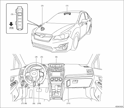
(1) | Stereo camera | (5) | EyeSight steering switch | (9) | Transmission control module (TCM) |
(2) | VDC control module (VDCCM) | (6) | MFD (multi-function display) | (10) | Stop light and brake switch |
(3) | Brake light relay | (7) | Body integrated unit | (11) | ECM |
(4) | Combination meter | (8) | Data link connector |
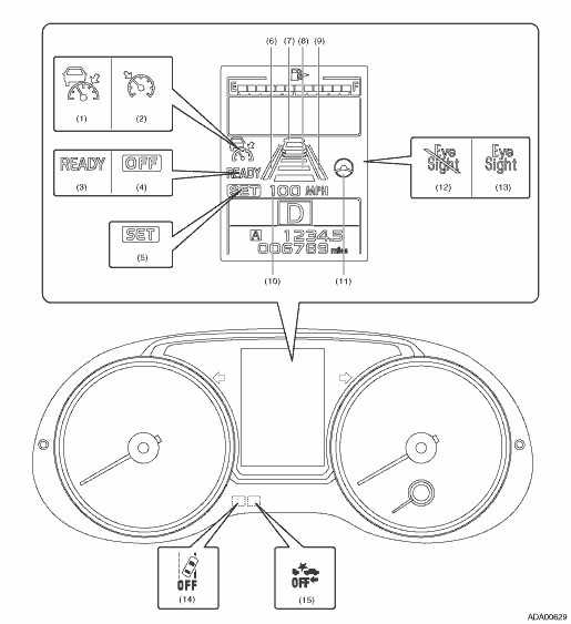
(1) | Adaptive cruise display | (6) | Lane indicator (left) | (11) | Steering wheel indicator |
(2) | Conventional cruise display | (7) | Preceding vehicle indicator | (12) | EyeSight temporary stop indicator |
(3) | READY indicator | (8) | Following distance setting indicator | (13) | EyeSight warning indicator |
(4) | OFF indicator | (9) | Lane indicator (right) | (14) | Lane departure warning OFF indicator light |
(5) | SET indicator | (10) | Set vehicle speed display | (15) | Pre-collision brake OFF indicator light |
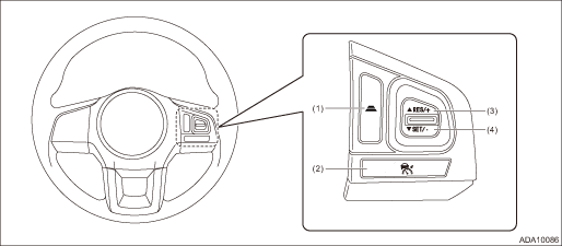
(1) | Following distance setting switch | (3) | RES/+ (resume/plus) switch | (4) | SET/− (set/minus) switch |
(2) | CRUISE switch |
 Clear memory mode Operation
EyeSight (DIAGNOSTICS) > Clear Memory ModeOPERATION1. On «Start» display, select «Diagnosis».2. On «Vehicle selection» display, input the target vehicle information and select «Confirmed».3 ...
 Read current data Operation
EyeSight (DIAGNOSTICS) > Read Current DataOPERATION1. STEREO CAMERA1. On «Start» display, select «Diagnosis».2. On «Vehicle selection» display, input the target vehicle information and select ...
Other materials:
Trailer safety chains
WARNING
Always use safety chains between
your vehicle and the trailer. Towing
trailer without safety chains could
create a traffic safety hazard if the
trailer separates from the hitch due
to coupling damage or hitch ball
damage.
In case the trailer hitch connector or hitch
ball should brea ...
Dtc p2109 throttle/pedal position sensor "a" minimum stop performance
ENGINE (DIAGNOSTICS)(H4DO) > Diagnostic Procedure with Diagnostic Trouble Code (DTC)DTC P2109 THROTTLE/PEDAL POSITION SENSOR "A" MINIMUM STOP PERFORMANCENOTE:For the diagnostic procedure, refer to DTC P2101. Diagnostic Procedure with Diagnostic Trouble Code (DTC) > DTC P2101 THROTTL ...
Refueling in cold weather
To help prevent moisture from forming in
the fuel system and the risk of its freezing,
use of an antifreeze additive in the fuel
tank is recommended during cold weather.
Use only additives that are specifically
designed for this purpose. When an
antifreeze additive is used, its effect lasts
...
