Subaru Crosstrek Service Manual: Dtc u1500 keyless uart com. Malfunction
BODY CONTROL SYSTEM (DIAGNOSTICS) > Diagnostic Procedure with Diagnostic Trouble Code (DTC)
DTC U1500 KEYLESS UART COM. MALFUNCTION
1. MODEL WITHOUT KEYLESS ACCESS WITH PUSH BUTTON START SYSTEM
DTC detecting condition:
UART between the TPMS & keyless control module or keyless entry CM and the body integrated unit is open or shorted, or has communication failure.
Trouble symptom:
Door lock does not operate with keyless.
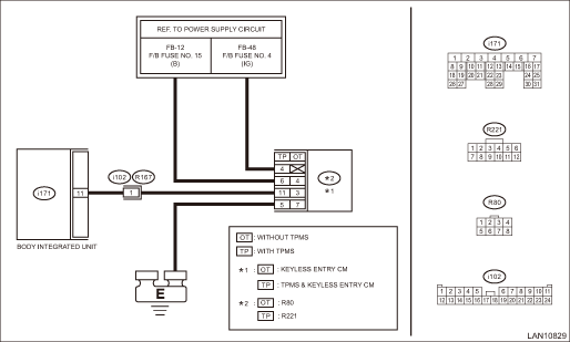
Wiring diagram:
Keyless entry system Keyless Entry System > WIRING DIAGRAM">
| STEP | CHECK | YES | NO |
1.CHECK DTC.
1) Insert the ignition key to the ignition key cylinder and remove.
2) Read the DTC of body integrated unit using Subaru Select Monitor. Read Diagnostic Trouble Code (DTC)">
Is U1500 a current malfunction?
Diagnostic Procedure with Diagnostic Trouble Code (DTC) > DTC U1500 KEYLESS UART COM. MALFUNCTION">Go to Step 2.
Diagnostic Procedure with Diagnostic Trouble Code (DTC) > DTC U1500 KEYLESS UART COM. MALFUNCTION">Go to Step 7.
2.CHECK DTC.
1) Turn the ignition switch to OFF.
2) Disconnect the body integrated unit and the TPMS & keyless control module or keyless entry CM connector.
3) Connect the disconnected connectors.
4) Insert the ignition key to the ignition key cylinder and remove.
5) Read the DTC of body integrated unit using Subaru Select Monitor. Read Diagnostic Trouble Code (DTC)">
Is U1500 a current malfunction?
Diagnostic Procedure with Diagnostic Trouble Code (DTC) > DTC U1500 KEYLESS UART COM. MALFUNCTION">Go to Step 3.
Diagnostic Procedure with Diagnostic Trouble Code (DTC) > DTC U1500 KEYLESS UART COM. MALFUNCTION">Go to Step 7.
3.CHECK HARNESS (OPEN CIRCUIT).
1) Turn the ignition switch to OFF.
2) Disconnect the body integrated unit and the TPMS & keyless control module or keyless entry CM connector.
3) Using the tester, measure the resistance between terminals.
Connector & terminal
With TPMS
(i171) No. 11 — (R221) No. 11:
Without TPMS
(i171) No. 11 — (R80) No. 3:
Is the resistance 10 ? or less?
Diagnostic Procedure with Diagnostic Trouble Code (DTC) > DTC U1500 KEYLESS UART COM. MALFUNCTION">Go to Step 4.
Repair the open circuit of harness or replace harness.
4.CHECK POWER SUPPLY CIRCUIT.
1) Turn the ignition switch to ON.
2) Use a tester to measure the voltage between the terminals.
Connector & terminal
With TPMS
(R221) No. 6 (+) — Chassis ground (−):
(R221) No. 4 (+) — Chassis ground (−):
Without TPMS
(R80) No. 4 (+) — Chassis ground (−):
Is the voltage 10 V or more?
Diagnostic Procedure with Diagnostic Trouble Code (DTC) > DTC U1500 KEYLESS UART COM. MALFUNCTION">Go to Step 5.
Repair the power supply circuit.
5.CHECK HARNESS (OPEN CIRCUIT).
Using the tester, measure the resistance between terminals.
Connector & terminal
With TPMS
(R221) No. 5 — Chassis ground:
Without TPMS
(R80) No. 7 — Chassis ground:
Is the resistance 10 ? or less?
Diagnostic Procedure with Diagnostic Trouble Code (DTC) > DTC U1500 KEYLESS UART COM. MALFUNCTION">Go to Step 6.
Repair the ground circuit.
6.CHECK DTC.
1) Connect all the disconnected connectors.
2) Turn the ignition switch to ON.
3) Read the DTC of body integrated unit using Subaru Select Monitor. Read Diagnostic Trouble Code (DTC)">
Is any DTC other than U1500 displayed?
Replace the body integrated unit. Body Integrated Unit">
Replace the TPMS & keyless control module or keyless entry CM. Keyless Entry Control Module > REMOVAL"> Tire Pressure Monitoring System > REMOVAL">
7.CHECK CONNECTOR.
Check for a poor contact between the body integrated unit and the TPMS & keyless control module or keyless entry CM connector.
Is there poor contact of connector?
Repair the connector that has poor contact, or replace harness.
Even if DTC is displayed, the circuit has returned to a normal condition at this time. Reproduce the failure, and then perform the diagnosis again.
NOTE:
In this case, temporary poor contact of connector, temporary open or short circuit of harness may be the cause.
2. MODEL WITH KEYLESS ACCESS WITH PUSH BUTTON START SYSTEM
DTC detecting condition:
UART between the TPMS CM and the body integrated unit is open or shorted, or has communication failure.
Trouble symptom:
Cannot communicate with TPMS CM.
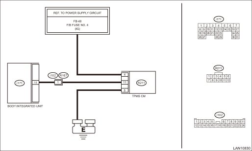
Wiring diagram:
Tire Pressure Monitoring System Tire Pressure Monitoring System > WIRING DIAGRAM">
| STEP | CHECK | YES | NO |
1.CHECK DTC.
1) With the access key in the vehicle, press the push button ignition switch twice without depressing the brake to turn the ignition switch to ON.
2) Read the DTC of body integrated unit using Subaru Select Monitor. Read Diagnostic Trouble Code (DTC)">
Is U1500 a current malfunction?
Diagnostic Procedure with Diagnostic Trouble Code (DTC) > DTC U1500 KEYLESS UART COM. MALFUNCTION">Go to Step 2.
Diagnostic Procedure with Diagnostic Trouble Code (DTC) > DTC U1500 KEYLESS UART COM. MALFUNCTION">Go to Step 7.
2.CHECK DTC.
1) Turn the ignition switch to OFF.
2) Disconnect the body integrated unit and the TPMS CM connector.
3) Connect the disconnected connectors.
4) With the access key in the vehicle, press the push button ignition switch twice without depressing the brake to turn the ignition switch to ON.
5) Read the DTC of body integrated unit using Subaru Select Monitor. Read Diagnostic Trouble Code (DTC)">
Is U1500 a current malfunction?
Diagnostic Procedure with Diagnostic Trouble Code (DTC) > DTC U1500 KEYLESS UART COM. MALFUNCTION">Go to Step 3.
Diagnostic Procedure with Diagnostic Trouble Code (DTC) > DTC U1500 KEYLESS UART COM. MALFUNCTION">Go to Step 7.
3.CHECK HARNESS (OPEN CIRCUIT).
1) Turn the ignition switch to OFF.
2) Disconnect the body integrated unit and the TPMS CM connector.
3) Using the tester, measure the resistance between terminals.
Connector & terminal
(i171) No. 11 — (R211) No. 11:
Is the resistance 10 ? or less?
Diagnostic Procedure with Diagnostic Trouble Code (DTC) > DTC U1500 KEYLESS UART COM. MALFUNCTION">Go to Step 4.
Repair the open circuit of harness or replace harness.
4.CHECK POWER SUPPLY CIRCUIT.
1) Turn the ignition switch to ON.
2) Use a tester to measure the voltage between the terminals.
Connector & terminal
(R211) No. 4 (+) — Chassis ground (−):
Is the voltage 10 V or more?
Diagnostic Procedure with Diagnostic Trouble Code (DTC) > DTC U1500 KEYLESS UART COM. MALFUNCTION">Go to Step 5.
Repair the power supply circuit.
5.CHECK HARNESS (OPEN CIRCUIT).
Using the tester, measure the resistance between terminals.
Connector & terminal
(R211) No. 5 — Chassis ground:
Is the resistance 10 ? or less?
Diagnostic Procedure with Diagnostic Trouble Code (DTC) > DTC U1500 KEYLESS UART COM. MALFUNCTION">Go to Step 6.
Repair the ground circuit.
6.CHECK DTC.
1) Connect all the disconnected connectors.
2) Turn the ignition switch to ON.
3) Read the DTC of body integrated unit using Subaru Select Monitor. Read Diagnostic Trouble Code (DTC)">
Is any DTC other than U1500 displayed?
Replace the body integrated unit. Body Integrated Unit">
Replace the TPMS CM. Tire Pressure Monitoring System > REMOVAL">
7.CHECK CONNECTOR.
Check for a poor contact between the body integrated unit and the TPMS CM connector.
Is there poor contact of connector?
Repair the connector that has poor contact, or replace harness.
Even if DTC is displayed, the circuit has returned to a normal condition at this time. Reproduce the failure, and then perform the diagnosis again.
NOTE:
In this case, temporary poor contact of connector, temporary open or short circuit of harness may be the cause.

 Dtc b1016 shift lock circuit
BODY CONTROL SYSTEM (DIAGNOSTICS) > Diagnostic Procedure with Diagnostic Trouble Code (DTC)DTC B1016 SHIFT LOCK CIRCUITDTC detecting condition:Open or power supply-output short, GND-output short in ...
Other materials:
Dtc b11f7 side impact deployment
AIRBAG SYSTEM (DIAGNOSTICS) > Diagnostic Chart with Trouble CodeDTC B11F7 SIDE IMPACT DEPLOYMENTDIAGNOSIS START CONDITION:Ignition voltage is 10 V to 16 V.DTC DETECTING CONDITION:This DTC is displayed when the side airbag module and curtain airbag module are deployed.Once this DTC is displayed, t ...
Removal
LIGHTING SYSTEM > Combination Switch (Light)REMOVALCAUTION:Before handling the airbag system components, refer to “CAUTION” of “General Description” in “AIRBAG SYSTEM”. General Description > CAUTION">1. Set the tire to the straight-ahead position.2. ...
Removal
FUEL INJECTION (FUEL SYSTEMS)(H4DO) > Fuel PumpREMOVALWARNING:Place “NO OPEN FLAMES” signs near the working area.CAUTION:• Be careful not to spill fuel.• Catch the fuel from the tubes using a container or cloth.• If the fuel gauge indicates that two thirds or more of ...
