Subaru Crosstrek Service Manual: Dtc p2530 ignition switch run position circuit
CONTINUOUSLY VARIABLE TRANSMISSION (DIAGNOSTICS) > Diagnostic Procedure with Diagnostic Trouble Code (DTC)
DTC P2530 IGNITION SWITCH RUN POSITION CIRCUIT
DTC detecting condition:
Immediately at fault recognition
Trouble symptom:
Faulty TCM operation
CAUTION:
Use the check board when measuring the TCM terminal voltage and resistance.
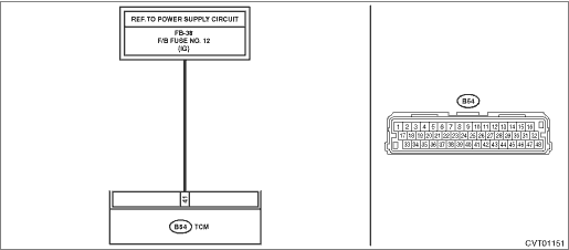
Wiring diagram:
CVT control system CVT Control System">

| STEP | CHECK | YES | NO |
1.CHECK CONNECTOR.
Check the installing condition of TCM connector.
Is the TCM connector installed properly?
Diagnostic Procedure with Diagnostic Trouble Code (DTC) > DTC P2530 IGNITION SWITCH RUN POSITION CIRCUIT">Go to Step 2.
Install the TCM connector.
2.CHECK INPUT VOLTAGE OF TCM.
1) Turn the ignition switch to OFF.
2) Disconnect the TCM connector.
3) Turn the ignition switch to ON.
4) Measure the voltage between TCM connector and chassis ground. (While wiggling the harness)
Connector & terminal
(B54) No. 41 (+) — Chassis ground (−):
Is the voltage 8 V or more?
Even if DTC is detected, the circuit has returned to a normal condition at this time. Reproduce the failure, and then perform the diagnosis again.
NOTE:
In this case, the following items may be the cause of fault.
• Open circuit or short circuit to ground of harness between TCM connector and ignition switch connector (IG relay 1 connector for model with push button start)
• Poor contact of ignition switch connector (IG relay 1 connector for model with push button start)
• Poor contact of ignition switch (IG relay 1 for model with push button start)
Repair the harness and connector.
NOTE:
In this case, repair the following item:
• Open circuit or short circuit to ground of harness between TCM connector and ignition switch connector (IG relay 1 connector for model with push button start)
• Poor contact of ignition switch connector (IG relay 1 connector for model with push button start)
• Poor contact of ignition switch (IG relay 1 for model with push button start)
1. OUTLINE OF DIAGNOSIS
• Detect the malfunction of ignition SW circuit.
• Judge as NG if the ignition SW signals are lost 5 times or more even though the engine is ON.
2. EXECUTION CONDITION
Secondary parameters | Execution condition |
12 V battery system voltage | ≥ 10.9 V |
Engine speed | ≥ 400 rpm |
3. DIAGNOSTIC METHOD
If the duration of time while the following conditions are met is longer than the time indicated, judge as NG.
Malfunction Criteria | Threshold Value |
Count of temporarily discontinuous input of ignition switch | ≥ 5 count |
Time Needed for Diagnosis: 5 seconds
Malfunction Indicator Light Illumination: Illuminates as soon as a malfunction occurs.
 Dtc p062f internal control module eeprom error
CONTINUOUSLY VARIABLE TRANSMISSION (DIAGNOSTICS) > Diagnostic Procedure with Diagnostic Trouble Code (DTC)DTC P062F INTERNAL CONTROL MODULE EEPROM ERRORDTC DETECTING CONDITION:Detected when two con ...
 Dtc p0601 internal control module memory checksum error
CONTINUOUSLY VARIABLE TRANSMISSION (DIAGNOSTICS) > Diagnostic Procedure with Diagnostic Trouble Code (DTC)DTC P0601 INTERNAL CONTROL MODULE MEMORY CHECKSUM ERRORDTC DETECTING CONDITION:Detected whe ...
Other materials:
Electrical component location Location
Blind Spot Detection/Rear Cross Traffic Alert (DIAGNOSTICS) > Electrical Component LocationLOCATION(1)Outer mirror assembly RH(3)Radar sensor RH (slave)(5)BSD/RCTA OFF switch(2)Outer mirror assembly LH(4)Radar sensor LH (master)(6)Data link connector ...
Installation
FUEL INJECTION (FUEL SYSTEMS)(H4DO) > Fuel Level SensorINSTALLATIONInstall in the reverse order of removal.CAUTION:Be sure to install the fuel level sensor harness to the clip first, then install the connector cable. Otherwise, malfunction may occur.(A)Fuel level sensor harness(B)Connector cable ...
Installation
CLUTCH SYSTEM > Release Bearing and LeverINSTALLATIONNOTE:Apply the specified grease to lubricate to the following points before installation.• Contact surface of lever and pivot• Contact surface of lever and bearing• Transmission main shaft spline• Contact surface of rele ...
