Subaru Crosstrek Service Manual: Dtc p2402 evap system leak detection pump control circuit high
ENGINE (DIAGNOSTICS)(H4DO) > Diagnostic Procedure with Diagnostic Trouble Code (DTC)
DTC P2402 EVAP SYSTEM LEAK DETECTION PUMP CONTROL CIRCUIT HIGH
DTC detecting condition:
Immediately at fault recognition
CAUTION:
After servicing or replacing faulty parts, perform Clear Memory Mode Clear Memory Mode > OPERATION"> , and Inspection Mode Inspection Mode > PROCEDURE">.
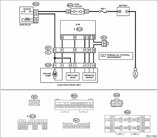
Wiring diagram:
Engine electrical system Engine Electrical System">
| STEP | CHECK | YES | NO |
1.CHECK HARNESS BETWEEN ECM AND LEAK CHECK VALVE ASSEMBLY CONNECTOR.
1) Turn the ignition switch to OFF.
2) Disconnect the connector from the leak check valve assembly.
3) Turn the ignition switch to ON.
4) Measure the voltage between leak check valve assembly and chassis ground.
Connector & terminal
(R400) No. 4 (+) — Chassis ground (−):
Is the voltage 10 V or more?
Repair the short circuit to power in harness between ECM connector and leak check valve assembly connector.
Diagnostic Procedure with Diagnostic Trouble Code (DTC) > DTC P2402 EVAP SYSTEM LEAK DETECTION PUMP CONTROL CIRCUIT HIGH">Go to Step 2.
2.CHECK LEAK CHECK VALVE ASSEMBLY.
1) Turn the ignition switch to OFF.
2) Check the vacuum pump of the leak check valve assembly. Leak Check Valve Assembly > INSPECTION">
Is the check result OK?
Repair the poor contact in the leak check valve assembly connector.
Replace the leak check valve assembly. Leak Check Valve Assembly">
1. OUTLINE OF DIAGNOSIS
Detect the open or short circuit in Evaporative Leak Check Module vacuum pump.
Judge as NG if out of specification.
2. COMPONENT DESCRIPTION
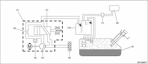
(1) | Leak check valve ASSY | (5) | Vacuum pump | (9) | Fuel tank |
(2) | Switching valve | (6) | Drain filter | (10) | Canister |
(3) | Reference orifice (0.02 inch orifice) | (7) | Purge control solenoid valve | ||
(4) | Pressure sensor | (8) | Intake manifold |
3. EXECUTION CONDITION
Secondary Parameters | Execution condition |
Battery voltage | ≥ 10.9 V |
Measured EVAP system leak detection pump current | ≥ 12 A |
4. GENERAL DRIVING CYCLE
Always perform the diagnosis continuously.
5. DIAGNOSTIC METHOD
If the duration of time while the following conditions are met is longer than the time indicated, judge as NG.
Malfunction Criteria | Threshold Value |
Battery voltage | ≥ 10.9 |
Terminal output voltage when ECM outputs ON signal | High |
Time Needed for Diagnosis: 2500 ms
Malfunction Indicator Light Illumination: Illuminates as soon as a malfunction occurs.
 Dtc p2401 evap system leak detection pump control circuit low
ENGINE (DIAGNOSTICS)(H4DO) > Diagnostic Procedure with Diagnostic Trouble Code (DTC)DTC P2401 EVAP SYSTEM LEAK DETECTION PUMP CONTROL CIRCUIT LOWDTC detecting condition:Immediately at fault recogni ...
 Dtc p2404 evap system leak detection pump sense circuit range/performance
ENGINE (DIAGNOSTICS)(H4DO) > Diagnostic Procedure with Diagnostic Trouble Code (DTC)DTC P2404 EVAP SYSTEM LEAK DETECTION PUMP SENSE CIRCUIT RANGE/PERFORMANCEDTC detecting condition:Detected when tw ...
Other materials:
Dtc p0400 egr "a" flow
ENGINE (DIAGNOSTICS)(H4DO) > Diagnostic Procedure with Diagnostic Trouble Code (DTC)DTC P0400 EGR "A" FLOWDTC detecting condition:Detected when two consecutive driving cycles with fault occur.Trouble symptom:• Movement performance problem when engine is low speed• Improper i ...
Preparation for date setting
Turn the ignition switch to the "ON"
position.
Push and hold the button to show
the selection screen.
After the selection screen is displayed,
operate the "
"
or "
" switch to show the
"Time/Date" item. Then, push the
button.
...
Dtc b1815 short in passenger s airbag dual stage - 2nd step
AIRBAG SYSTEM (DIAGNOSTICS) > Diagnostic Chart with Trouble CodeDTC B1815 SHORT IN PASSENGER’S AIRBAG DUAL STAGE - 2ND STEPDiagnosis start condition:Ignition voltage is 10 V to 16 V.DTC detecting condition:• Airbag main harness circuit is shorted.• Airbag module harness circuit ...
