Subaru Crosstrek Service Manual: Dtc p2138 throttle/pedal position sensor/switch "d"/"e" voltage correlation
ENGINE (DIAGNOSTICS)(H4DO) > Diagnostic Procedure with Diagnostic Trouble Code (DTC)
DTC P2138 THROTTLE/PEDAL POSITION SENSOR/SWITCH "D"/"E" VOLTAGE CORRELATION
DTC DETECTING CONDITION:
Immediately at fault recognition
TROUBLE SYMPTOM:
• Improper idling
• Poor driving performance
CAUTION:
After servicing or replacing faulty parts, perform Clear Memory Mode Clear Memory Mode > OPERATION"> , and Inspection Mode Inspection Mode > PROCEDURE">.
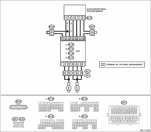
WIRING DIAGRAM:
Engine electrical system Engine Electrical System">
| STEP | CHECK | YES | NO |
1.CHECK ACCELERATOR PEDAL POSITION SENSOR OUTPUT.
1) Turn the ignition switch to ON.
2) Measure the voltage between ECM connector and chassis ground.
Connector & terminal
Main accelerator pedal position sensor signal
(B135) No. 23 (+) — Chassis ground (−):
Sub accelerator pedal position sensor signal
(B135) No. 31 (+) — Chassis ground (−):
Is the difference in measured values for the main accelerator pedal position sensor signal and the sub accelerator pedal position sensor signal 0 V?
Diagnostic Procedure with Diagnostic Trouble Code (DTC) > DTC P2138 THROTTLE/PEDAL POSITION SENSOR/SWITCH "D"/"E" VOLTAGE CORRELATION">Go to Step 3.
Diagnostic Procedure with Diagnostic Trouble Code (DTC) > DTC P2138 THROTTLE/PEDAL POSITION SENSOR/SWITCH "D"/"E" VOLTAGE CORRELATION">Go to Step 2.
2.CHECK ACCELERATOR PEDAL POSITION SENSOR OUTPUT.
1) Measure the voltage between accelerator pedal position sensor connector and chassis ground.
Connector & terminal
(B315) No. 6 (+) — Chassis ground (−):
(B315) No. 3 (+) — Chassis ground (−):
Is the difference in measured values for the main accelerator pedal position sensor signal and the sub accelerator pedal position sensor signal 0 V?
Replace the accelerator pedal. Accelerator Pedal">
Repair the harness and connector.
NOTE:
In this case, repair the following item:
• Open circuit of harness between ECM connector and accelerator pedal position sensor connector
• Short circuit to ground in harness between ECM connector and accelerator pedal position sensor connector
3.CHECK HARNESS BETWEEN ECM AND ACCELERATOR PEDAL POSITION SENSOR CONNECTOR.
Measure the resistance of harness between accelerator pedal position sensor connector and chassis ground.
Connector & terminal
(B315) No. 5 — Chassis ground:
(B315) No. 2 — Chassis ground:
Is the resistance less than 5 ??
Repair the poor contact of ECM connector.
Repair the harness and connector.
NOTE:
In this case, repair the following item:
• Open circuit of harness between ECM connector and accelerator pedal position sensor connector
• Open circuit of harness between ECM connector and engine ground
• Poor contact of ECM connector
• Poor contact of joint connector
1. OUTLINE OF DIAGNOSIS
Judge as NG when the signal level of accelerator pedal position sensor 1 is different from the accelerator pedal position sensor 2.
2. COMPONENT DESCRIPTION
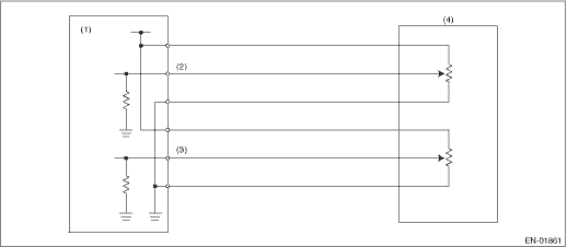
(1) | Engine control module (ECM) | (3) | Accelerator pedal position sensor 2 signal | (4) | Accelerator pedal position sensor |
(2) | Accelerator pedal position sensor 1 signal |
3. EXECUTION CONDITION
Secondary Parameters | Execution condition |
Battery voltage | ≥ 6 V |
4. GENERAL DRIVING CYCLE
Always perform the diagnosis continuously.
5. DIAGNOSTIC METHOD
If the duration of time while the following conditions are met is longer than the time indicated, judge as NG.
Malfunction Criteria | Threshold Value |
Signal difference between two sensors | Within NG range of Details of Judgment value |
Details of Judgment Value
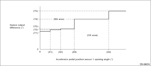
(X1) | 0.6 ° | (X2) | 1.2 ° | (X3) | 2 ° |
(X4) | 4 ° | ||||
(Y1) | 1.465 ° | (Y2) | 1.597 ° | (Y3) | 1.663 ° |
(Y4) | 2.455 ° | (Y5) | 3.116 ° |
Time Needed for Diagnosis: 116 ms
Malfunction Indicator Light Illumination: Illuminates as soon as a malfunction occurs.
 Dtc p2135 throttle/pedal position sensor/switch "a"/"b" voltage correlation
ENGINE (DIAGNOSTICS)(H4DO) > Diagnostic Procedure with Diagnostic Trouble Code (DTC)DTC P2135 THROTTLE/PEDAL POSITION SENSOR/SWITCH "A"/"B" VOLTAGE CORRELATIONDTC detecting cond ...
 Dtc p2195 a/f /o2 sensor signal biased/stuck lean bank 1 sensor 1
ENGINE (DIAGNOSTICS)(H4DO) > Diagnostic Procedure with Diagnostic Trouble Code (DTC)DTC P2195 A/F /O2 SENSOR SIGNAL BIASED/STUCK LEAN BANK 1 SENSOR 1DTC detecting condition:Detected when two consec ...
Other materials:
Inspection
Blind Spot Detection/Rear Cross Traffic Alert (DIAGNOSTICS) > General DescriptionINSPECTION1. BASIC INSPECTIONBefore performing diagnosis, check the following items that might provoke the problems related to BSD/RCTA.1. Check the battery. Battery">2. Check the relay and fuse condition. ...
Component
DRIVE SHAFT SYSTEM > General DescriptionCOMPONENT1. PROPELLER SHAFT(1)Propeller shaft(3)Rear differential (T-type)Tightening torque: N·m (kgf-m, ft-lb)(2)Rear differential (VA1-type) T1:31 (3.2, 22.9) T2:52 (5.3, 38.4)2. FRONT AXLE• EBJ + PTJ type(1)Circlip(8)Boot (PTJ)(15)Front ...
Installation
POWER ASSISTED SYSTEM (POWER STEERING) > Steering ColumnINSTALLATIONCAUTION:If the steering wheel and steering angle sensor are removed, perform the following VDC setting mode.– Model without EyeSight: VDC sensor midpoint setting mode VDC Control Module and Hydraulic Control Unit (VDCCM&H ...
