Subaru Crosstrek Service Manual: Dtc p1532 battery charging system
ENGINE (DIAGNOSTICS)(H4DO) > Diagnostic Procedure with Diagnostic Trouble Code (DTC)
DTC P1532 BATTERY CHARGING SYSTEM
DTC detecting condition:
Immediately at fault recognition
CAUTION:
After servicing or replacing faulty parts, perform Clear Memory Mode Clear Memory Mode > OPERATION"> , and Inspection Mode Inspection Mode > PROCEDURE">.
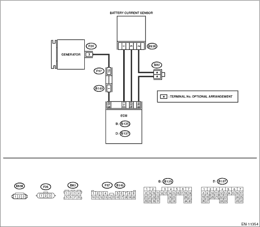
Wiring diagram:
Engine electrical system Engine Electrical System">
| STEP | CHECK | YES | NO |
1.CHECK INSTALLATION CONDITION OF BATTERY.
Turn the ignition switch to OFF.
Are the positive and negative terminals of battery securely tightened?
Diagnostic Procedure with Diagnostic Trouble Code (DTC) > DTC P1532 BATTERY CHARGING SYSTEM">Go to Step 2.
Tighten the positive and negative terminals of battery securely.
2.CHECK BATTERY TERMINAL.
Is there any connection of electrical parts to the positive and negative terminals of battery?
Remove the wiring of electrical parts connected to the positive and negative terminals of battery.
NOTE:
Directly connecting electrical parts to the battery may cause erroneous operation of the battery current sensor.
Diagnostic Procedure with Diagnostic Trouble Code (DTC) > DTC P1532 BATTERY CHARGING SYSTEM">Go to Step 3.
3.CHECK INSTALLATION CONDITION OF V-BELT.
Check the installation condition of V-belt. V-belt > INSPECTION">
Is the V-belt installed properly?
Diagnostic Procedure with Diagnostic Trouble Code (DTC) > DTC P1532 BATTERY CHARGING SYSTEM">Go to Step 4.
Install the V-belt properly. V-belt">
4.CHECK BATTERY VOLTAGE.
1) Start the engine.
2) Select «High mode» in «Alternator control» from «Active Test» items, and measure the battery voltage after 10 seconds have passed.
NOTE:
For detailed operation procedures, refer to the “Active Test”. Active Test">
3) Select «Low mode» in «Alternator control» from «Active Test» items, and measure the battery voltage.
CAUTION:
Do not continue the “Low mode” operation for one minute or more.
NOTE:
For detailed operation procedures, refer to the “Active Test”. Active Test">
Does battery voltage lower from 13.9 — 14.8 V to 12.2 — 13.1 V between step 2) and step 3)?
Diagnostic Procedure with Diagnostic Trouble Code (DTC) > DTC P1532 BATTERY CHARGING SYSTEM">Go to Step 7.
Diagnostic Procedure with Diagnostic Trouble Code (DTC) > DTC P1532 BATTERY CHARGING SYSTEM">Go to Step 5.
5.CHECK HARNESS BETWEEN ECM AND GENERATOR CONNECTOR.
1) Turn the ignition switch to OFF.
2) Disconnect the connector from ECM.
3) Disconnect the connector from the generator.
4) Measure the resistance of harness between ECM connector and generator connector.
Connector & terminal
(B135) No. 18 — (F26) No. 3:
Is the resistance less than 1 ??
Diagnostic Procedure with Diagnostic Trouble Code (DTC) > DTC P1532 BATTERY CHARGING SYSTEM">Go to Step 6.
Repair the open circuit of harness between ECM connector and generator connector.
6.CHECK HARNESS BETWEEN ECM AND GENERATOR CONNECTOR.
Measure the resistance between generator connector and engine ground.
Connector & terminal
(F26) No. 3 — Engine ground:
Is the resistance 1 M? or more?
Diagnostic Procedure with Diagnostic Trouble Code (DTC) > DTC P1532 BATTERY CHARGING SYSTEM">Go to Step 7.
Repair the ground short circuit of harness between ECM connector and generator connector.
7.CHECK BATTERY CURRENT SENSOR.
Has water entered the connector?
Completely remove any water inside.
Diagnostic Procedure with Diagnostic Trouble Code (DTC) > DTC P1532 BATTERY CHARGING SYSTEM">Go to Step 8.
8.CHECK HARNESS BETWEEN ECM AND BATTERY CURRENT SENSOR CONNECTOR.
1) Disconnect the connector from ECM.
2) Disconnect the connector from the battery current sensor.
3) Measure the resistance of the harness between ECM connector and battery current sensor connector.
Connector & terminal
(B135) No. 22 — (B538) No. 3:
(B137) No. 11 — (B538) No. 1:
Is the resistance less than 1 ??
Diagnostic Procedure with Diagnostic Trouble Code (DTC) > DTC P1532 BATTERY CHARGING SYSTEM">Go to Step 9.
Repair the open circuit in the harness between ECM connector and battery current sensor connector.
9.CHECK HARNESS BETWEEN ECM AND BATTERY CURRENT SENSOR CONNECTOR.
Measure the resistance between ECM connector and chassis ground.
Connector & terminal
(B135) No. 22 — Chassis ground:
(B137) No. 11 — Chassis ground:
Is the resistance 1 M? or more?
Diagnostic Procedure with Diagnostic Trouble Code (DTC) > DTC P1532 BATTERY CHARGING SYSTEM">Go to Step 10.
Repair the short circuit to ground in the harness between ECM connector and battery current sensor connector.
10.CHECK HARNESS BETWEEN ECM AND BATTERY CURRENT SENSOR CONNECTOR.
Measure the resistance between ECM connectors.
Connector & terminal
(B135) No. 22 — (B136) No. 32:
Is the resistance 1 M? or more?
Diagnostic Procedure with Diagnostic Trouble Code (DTC) > DTC P1532 BATTERY CHARGING SYSTEM">Go to Step 11.
Repair the short circuit to power in the harness between ECM connector and battery current sensor connector.
11.CHECK HARNESS BETWEEN ECM AND BATTERY CURRENT SENSOR CONNECTOR.
1) Connect the connector to ECM.
2) Measure the resistance of the harness between the battery current sensor connector and engine ground.
Connector & terminal
(B538) No. 2 — Engine ground:
Is the resistance less than 5 ??
Diagnostic Procedure with Diagnostic Trouble Code (DTC) > DTC P1532 BATTERY CHARGING SYSTEM">Go to Step 12.
Repair the harness and connector.
NOTE:
In this case, repair the following item:
• Open circuit in harness between ECM connector and battery current sensor connector
• Poor contact of joint connector
12.CHECK FOR POOR CONTACT.
Check for poor contact of the battery current sensor connector.
Is there poor contact of the battery current sensor connector?
Repair the poor contact of the battery current sensor connector.
Replace the battery current sensor. Battery Current & Temperature Sensor">
1. OUTLINE OF DIAGNOSIS
Detect the output property and malfunction of battery current sensor.
Judge as NG when there is no variation (stuck) under a condition where the battery current sensor output should have changed or when difference between output and battery current value is larger than expected (characteristics malfunction).
2. COMPONENT DESCRIPTION
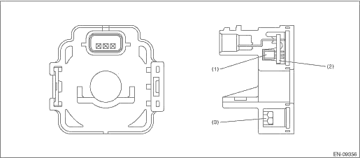
(1) | Hall IC | (2) | Chip condenser | (3) | Core |
3. EXECUTION CONDITION
• Stuck
Secondary Parameters | Execution condition |
Ignition switch | ON |
During switchover of regulating voltage | High condition judgment*1 ←> Low condition judgment*2 However, the generator target duty has not experienced the following during switchover. 40 % ≤ Generator target duty < 60 % |
*1 High condition judgment | |
Continuous time during which all the conditions listed below are met | ≥ 5000 ms |
• Battery voltage | ≥ 13.7 V |
• Generator final output duty | ≥ 60 % |
• Engine speed | ≥ 600 rpm |
*2 Low condition judgment | |
Continuous time during which all the conditions listed below are met | ≥ 5000 ms |
• Battery voltage | < 13.2 V |
• Generator final output duty | < 40 % |
or | |
• Engine speed | < 600 rpm |
• Characteristics malfunction
Secondary Parameters | Execution condition |
Ignition switch | ON |
During switchover of regulating voltage | High condition judgment is established. Target duty ≥ 60 % > target duty < 40 % or Low condition judgment is established. Target duty < 40 % > target duty ≥ 60 % |
4. GENERAL DRIVING CYCLE
Always perform the diagnosis continuously.
5. DIAGNOSTIC METHOD
• Stuck
Judge as NG when the following conditions are repeated 10 time(s) or more.
Malfunction Criteria | Threshold Value |
Difference between maximum value and minimum value in output voltage | < 0.07 V |
Time needed for diagnosis: Less than 1 second
Malfunction indicator light illumination: Does not illuminate even when malfunction occurs.
• Characteristics malfunction (Charge side)
Within 30000 ms from “enable condition not met” to “enable condition met”, judge as NG when the time required for meeting the following conditions exceeds the predetermined time.
(When NG judgment is performed, NG status is retained during that driving cycle.)
Malfunction Criteria | Threshold Value |
Output voltage | 2.6 V ≤ Output voltage < 5 V |
and | |
Battery voltage | < 13.2 V |
Time needed for diagnosis: 26000 ms
Malfunction indicator light illumination: Does not illuminate even when malfunction occurs.
• Characteristics malfunction (Discharge side)
Within 30000 ms from “enable condition not met” to “enable condition met”, judge as NG when the time required for meeting the following conditions exceeds the predetermined time.
(Within 30000 ms from “enable condition not met” to “enable condition met”, the target duty ≥ 60 % has not been experienced.)
Malfunction Criteria | Threshold Value |
Output voltage | 0 V ≤ Output voltage < 2.4 V |
and | |
Battery voltage | ≥ 13.7 V |
Time needed for diagnosis: 26000 ms
Malfunction indicator light illumination: Does not illuminate even when malfunction occurs.
 Dtc p0128 coolant thermostat (engine coolant temperature below thermostat regulating temperature)
ENGINE (DIAGNOSTICS)(H4DO) > Diagnostic Procedure with Diagnostic Trouble Code (DTC)DTC P0128 COOLANT THERMOSTAT (ENGINE COOLANT TEMPERATURE BELOW THERMOSTAT REGULATING TEMPERATURE)DTC detecting co ...
 Dtc p0301 cylinder 1 misfire detected
ENGINE (DIAGNOSTICS)(H4DO) > Diagnostic Procedure with Diagnostic Trouble Code (DTC)DTC P0301 CYLINDER 1 MISFIRE DETECTEDNOTE:For the diagnostic procedure, refer to DTC P0304. Diagnostic Procedure ...
Other materials:
Assembly
WIPER AND WASHER SYSTEMS > Wiper BladeASSEMBLY1. FRONT1. Insert the rubber assembly - windshield wiper onto the blade - windshield wiper so that the stopper is in the position shown in the figure.2. Make sure the rubber assembly - windshield wiper is securely fastened to the pull stopper (a).2. R ...
Removal
DRIVE SHAFT SYSTEM > Propeller ShaftREMOVALCAUTION:• Before removing propeller shaft, wrap metal parts with a cloth or rubber material.• Do not disassemble the center EDJ of the propeller shaft.• Before removing propeller shaft, wrap the metal parts attached to the rubber boot o ...
Cooling fan, hose and connections
Your vehicle employs an electric cooling
fan which is thermostatically controlled to
operate when the engine coolant reaches
a specific temperature.
If the radiator cooling fan does not operate
even when the coolant temperature high
warning light blinks or illuminates in RED,
the cooling fa ...
