Subaru Crosstrek Service Manual: Dtc p1531 battery current sensor circuit high
ENGINE (DIAGNOSTICS)(H4DO) > Diagnostic Procedure with Diagnostic Trouble Code (DTC)
DTC P1531 BATTERY CURRENT SENSOR CIRCUIT HIGH
DTC detecting condition:
Immediately at fault recognition
CAUTION:
After servicing or replacing faulty parts, perform Clear Memory Mode Clear Memory Mode > OPERATION"> , and Inspection Mode Inspection Mode > PROCEDURE">.
Wiring diagram:
Engine electrical system Engine Electrical System">

| STEP | CHECK | YES | NO |
1.CHECK CURRENT DATA.
1) Start the engine.
2) Read the value of «Battery current value» using the Subaru Select Monitor.
NOTE:
For detailed operation procedures, refer to “Current Data Display For Engine”. Subaru Select Monitor">
Is the value of «Battery current value» 100 A or more?
Diagnostic Procedure with Diagnostic Trouble Code (DTC) > DTC P1531 BATTERY CURRENT SENSOR CIRCUIT HIGH">Go to Step 2.
Even if DTC is detected, the circuit has returned to a normal condition at this time. Reproduce the failure, and then perform the diagnosis again.
NOTE:
In this case, temporary poor contact of connector, temporary open or short circuit of harness may be the cause.
2.CHECK HARNESS BETWEEN ECM AND BATTERY CURRENT SENSOR CONNECTOR.
1) Turn the ignition switch to OFF.
2) Disconnect the connector from the battery current sensor.
3) Start the engine.
4) Read the value of «Battery current value» using the Subaru Select Monitor.
NOTE:
For detailed operation procedures, refer to “Current Data Display For Engine”. Subaru Select Monitor">
Is the value of «Battery current value» 100 A or more?
Repair the short circuit to power in the harness between ECM connector and battery current sensor connector.
Diagnostic Procedure with Diagnostic Trouble Code (DTC) > DTC P1531 BATTERY CURRENT SENSOR CIRCUIT HIGH">Go to Step 3.
3.CHECK HARNESS BETWEEN ECM AND BATTERY CURRENT SENSOR CONNECTOR.
1) Turn the ignition switch to OFF.
2) Measure the resistance of the harness between the battery current sensor connector and engine ground.
Connector & terminal
(B538) No. 2 — Engine ground:
Is the resistance less than 5 ??
Diagnostic Procedure with Diagnostic Trouble Code (DTC) > DTC P1531 BATTERY CURRENT SENSOR CIRCUIT HIGH">Go to Step 4.
Repair the harness and connector.
NOTE:
In this case, repair the following item:
• Open circuit in harness between ECM connector and battery current sensor connector
• Poor contact of joint connector
4.CHECK FOR POOR CONTACT.
Check for poor contact of the battery current sensor connector.
Is there poor contact of the battery current sensor connector?
Repair the poor contact of the battery current sensor connector.
Replace the battery current sensor. Battery Current & Temperature Sensor">
1. OUTLINE OF DIAGNOSIS
Detect the open or short circuit of battery current sensor.
Judge as NG if out of specification.
2. COMPONENT DESCRIPTION
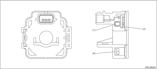
(1) | Hall IC | (2) | Chip condenser | (3) | Core |
3. EXECUTION CONDITION
Secondary Parameters | Execution condition |
Battery voltage | ≥ 10.9 V |
Elapsed time after starting the engine | > 1000 ms |
Engine speed | > 500 rpm |
Ignition switch | ON |
4. GENERAL DRIVING CYCLE
Always perform the diagnosis continuously.
5. DIAGNOSTIC METHOD
If the duration of time while the following conditions are met is longer than the time indicated, judge as NG.
Malfunction Criteria | Threshold Value |
Output voltage | ≥ 4.717 V |
Time Needed for Diagnosis: 500 ms
Malfunction Indicator Light Illumination: Does not illuminate even when malfunction occurs.
 Dtc p1530 battery current sensor circuit low
ENGINE (DIAGNOSTICS)(H4DO) > Diagnostic Procedure with Diagnostic Trouble Code (DTC)DTC P1530 BATTERY CURRENT SENSOR CIRCUIT LOWDTC detecting condition:Immediately at fault recognitionCAUTION:After ...
 Dtc u0101 lost communication with tcm
ENGINE (DIAGNOSTICS)(H4DO) > Diagnostic Procedure with Diagnostic Trouble Code (DTC)DTC U0101 LOST COMMUNICATION WITH TCMNOTE:For the diagnostic procedure, refer to LAN section. Basic Diagnostic P ...
Other materials:
Removal
LIGHTING SYSTEM > Front Fog Light AssemblyREMOVAL1. Disconnect the ground cable from battery. NOTE">2. Lift up the vehicle.3. Remove the screw and clips, and turn over the front side of the mud guard - front.4. From the bottom of the bumper face - front, remove the fog light assembly - f ...
Service diagnostics mode Operation
ENTERTAINMENT > Service Diagnostics ModeOPERATIONNOTE:Installed only to model with 7 inch display.1. PROCEDURE TO SWITCH TO SERVICE DIAGNOSTICS MODE1. Turn the ignition switch to ACC.2. After turning the ignition switch to ACC and wait for 20 seconds or more, press the button (b) five times with ...
General diagnostic table Inspection
REAR SUSPENSION > General Diagnostic TableINSPECTION1. IMPROPER VEHICLE POSTURE OR IMPROPER WHEEL ARCH HEIGHTPossible causeCorrective action(1) Permanent distortion or damaged coil springReplace.(2) Rough operation of shock absorberReplace.(3) Installation of the wrong shock absorberReplace with ...
