Subaru Crosstrek Service Manual: Dtc p0852 park/neutral switch input circuit high
ENGINE (DIAGNOSTICS)(H4DO) > Diagnostic Procedure with Diagnostic Trouble Code (DTC)
DTC P0852 PARK/NEUTRAL SWITCH INPUT CIRCUIT HIGH
1. AT MODEL
DTC detecting condition:
Detected when two consecutive driving cycles with fault occur.
Trouble symptom:
Improper idling
CAUTION:
After servicing or replacing faulty parts, perform Clear Memory Mode Clear Memory Mode > OPERATION"> , and Inspection Mode Inspection Mode > PROCEDURE">.
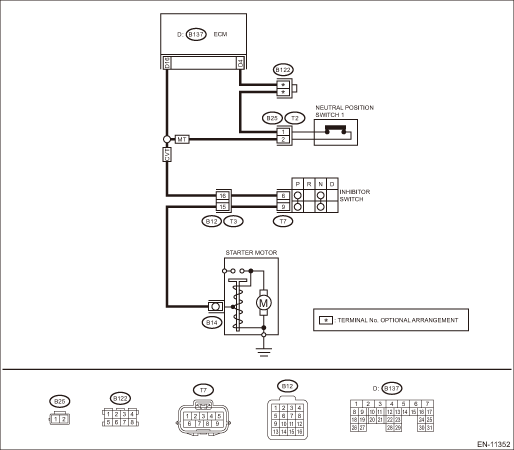
Wiring diagram:
Engine electrical system Engine Electrical System">
| STEP | CHECK | YES | NO |
1.CHECK SELECT CABLE.
Is there any fault in select cable?
Repair or adjust the select cable. Select Cable">
Diagnostic Procedure with Diagnostic Trouble Code (DTC) > DTC P0852 PARK/NEUTRAL SWITCH INPUT CIRCUIT HIGH">Go to Step 2.
2.CHECK INPUT SIGNAL OF ECM.
1) Turn the ignition switch to ON.
2) Measure the voltage between ECM and chassis ground with select lever at “P” range and “N” range.
Connector & terminal
(B137) No. 16 (+) — Chassis ground (−):
Is the voltage less than 1 V?
Repair the poor contact of ECM connector.
Diagnostic Procedure with Diagnostic Trouble Code (DTC) > DTC P0852 PARK/NEUTRAL SWITCH INPUT CIRCUIT HIGH">Go to Step 3.
3.CHECK HARNESS BETWEEN ECM AND INHIBITOR SWITCH CONNECTOR.
1) Turn the ignition switch to OFF.
2) Disconnect the connector from ECM.
3) Disconnect the connector from inhibitor switch.
4) Measure the resistance of harness between ECM connector and inhibitor switch connector.
Connector & terminal
(B137) No. 16 — (T7) No. 6:
Is the resistance less than 1 ??
Diagnostic Procedure with Diagnostic Trouble Code (DTC) > DTC P0852 PARK/NEUTRAL SWITCH INPUT CIRCUIT HIGH">Go to Step 4.
Repair the harness and connector.
NOTE:
In this case, repair the following item:
• Open circuit in harness between ECM connector and inhibitor switch connector
• Poor contact of coupling connector
4.CHECK INHIBITOR SWITCH GROUND LINE.
Measure the resistance of harness between inhibitor switch connector and engine ground.
Connector & terminal
(T7) No. 9 — Engine ground:
Is the resistance less than 5 ??
Replace the inhibitor switch. Inhibitor Switch">
Repair the harness and connector.
NOTE:
In this case, repair the following item:
• Open circuit of harness between inhibitor switch connector and starter motor ground line
• Poor contact of coupling connector
• Poor contact of starter motor connector
• Poor contact of starter motor ground
• Starter motor
2. OUTLINE OF DIAGNOSIS
Detect the open or short circuit of neutral SW.
Judge as NG when the ECM neutral terminal input differs from the reception data from TCM.
3. EXECUTION CONDITION
Secondary Parameters | Execution condition |
Battery voltage | ≥ 10.9 V |
Starter relay feedback voltage | < Battery voltage ? 0.35 |
Data received from TCM | ≠ “P” range/“N” range |
4. GENERAL DRIVING CYCLE
Perform the diagnosis continuously in 2 seconds after starting the engine.
5. DIAGNOSTIC METHOD
If the duration of time while the following conditions are met is longer than the time indicated, judge as NG.
Malfunction Criteria | Threshold Value |
Neutral position switch voltage | ≤ Battery voltage ? 0.6 |
Time Needed for Diagnosis: 64 ms ? 100 time(s)
Malfunction Indicator Light Illumination: Illuminates when malfunction occurs in 2 continuous driving cycles.
6. MT MODEL
DTC detecting condition:
Detected when two consecutive driving cycles with fault occur.
Trouble symptom:
Improper idling
CAUTION:
After servicing or replacing faulty parts, perform Clear Memory Mode Clear Memory Mode > OPERATION">, and Inspection Mode Inspection Mode > PROCEDURE">.
Wiring diagram:
Engine electrical system Engine Electrical System">
| STEP | CHECK | YES | NO |
1.CHECK INPUT SIGNAL OF ECM.
1) Turn the ignition switch to ON.
2) Place the gear shift lever in neutral.
3) Measure the voltage between ECM connector and chassis ground.
Connector & terminal
(B136) No. 35 (+) — Chassis ground (−):
Is the voltage less than 1 V?
Repair the poor contact of ECM connector.
Diagnostic Procedure with Diagnostic Trouble Code (DTC) > DTC P0852 PARK/NEUTRAL SWITCH INPUT CIRCUIT HIGH">Go to Step 2.
2.CHECK HARNESS BETWEEN ECM AND NEUTRAL POSITION SWITCH 1 CONNECTOR.
1) Turn the ignition switch to OFF.
2) Disconnect the connector from ECM.
3) Disconnect the connector from neutral position switch 1.
4) Measure the resistance of harness between ECM connector and neutral position switch 1 connector.
Connector & terminal
(B137) No. 16 — (B25) No. 2:
(B137) No. 4 — (B25) No. 1:
Is the resistance less than 1 ??
Diagnostic Procedure with Diagnostic Trouble Code (DTC) > DTC P0852 PARK/NEUTRAL SWITCH INPUT CIRCUIT HIGH">Go to Step 3.
Repair the harness and connector.
NOTE:
In this case, repair the following item:
• Open circuit in harness between ECM connector and neutral position switch 1 connector
• Poor contact of coupling connector
3.CHECK NEUTRAL POSITION SWITCH 1.
1) Place the gear shift lever in neutral.
2) Measure the resistance between neutral position switch 1 terminals.
Terminals
No. 1 — No. 2:
Is the resistance less than 1 ??
Repair the poor contact of neutral position switch 1 connector.
Replace the neutral position switch 1. Switches and Harness">
7. OUTLINE OF DIAGNOSIS
Detect the open or short circuit of neutral SW.
Judge as NG when there is no change in the neutral SW even if the driving shift was applied. (There is neutral SW ON/OFF inversion from the vehicle speed and engine speed.)
8. EXECUTION CONDITION
Secondary parameters | Execution condition |
Battery voltage | ≥ 10.9 V |
The number of driving condition change from a) to b) | = 3 time(s) |
a) | |
Vehicle speed | ≤ 0 km/h (0 MPH) |
and | |
Engine speed |
≥ 550 rpm and ≤ 850 rpm |
b) | |
Vehicle speed | ≥ 64 km/h (39.8 MPH) |
and | |
Engine speed |
≥ 1550 rpm and ≤ 2100 rpm |
9. GENERAL DRIVING CYCLE
Perform the diagnosis continuously in 2 seconds after starting the engine.
10. DIAGNOSTIC METHOD
Judge NG when the malfunction criteria below are completed determined times or more after the neutral SW change.
Malfunction Criteria | Threshold Value |
Neutral switch output voltage | ≥ Battery voltage ? 0.6 V |
Time Needed for Diagnosis: 3 time(s)
Malfunction Indicator Light Illumination: Illuminates when malfunction occurs in 2 continuous driving cycles.
 Dtc p219a bank 1 air-fuel ratio imbalance
ENGINE (DIAGNOSTICS)(H4DO) > Diagnostic Procedure with Diagnostic Trouble Code (DTC)DTC P219A BANK 1 AIR-FUEL RATIO IMBALANCEDTC detecting condition:Detected when two consecutive driving cycles wit ...
 Dtc p0516 battery temperature sensor circuit low
ENGINE (DIAGNOSTICS)(H4DO) > Diagnostic Procedure with Diagnostic Trouble Code (DTC)DTC P0516 BATTERY TEMPERATURE SENSOR CIRCUIT LOWDTC detecting condition:Immediately at fault recognitionCAUTION:A ...
Other materials:
Fastening the seatbelt
WARNING
Never use a belt that is twisted or
reversed. In an accident, this can
increase the risk or severity of
injury.
Keep the lap belt as low as
possible on your hips. In a collision,
this spreads the force of the
lap belt over stronger hip bones
instead of across the weaker
...
Inspection
COOLING(H4DO) > RadiatorINSPECTION1. Check that the radiator does not have deformation, cracks or damage.2. Check that the hose has no cracks, damage or loose part.3. Remove the radiator cap, fill the radiator with engine coolant, and then install the radiator cap tester to the filler neck of rad ...
Installation
SECURITY AND LOCKS > Starter Relay (Push Button Start)INSTALLATIONCAUTION:Before handling the airbag system components, refer to “CAUTION” of “General Description” in “AIRBAG SYSTEM”. General Description > CAUTION">Install each part in the reverse o ...
