Subaru Crosstrek Service Manual: Dtc p0851 park/neutral switch input circuit low
ENGINE (DIAGNOSTICS)(H4DO) > Diagnostic Procedure with Diagnostic Trouble Code (DTC)
DTC P0851 PARK/NEUTRAL SWITCH INPUT CIRCUIT LOW
1. AT MODEL
DTC detecting condition:
Detected when two consecutive driving cycles with fault occur.
Trouble symptom:
Improper idling
CAUTION:
After servicing or replacing faulty parts, perform Clear Memory Mode Clear Memory Mode > OPERATION"> , and Inspection Mode Inspection Mode > PROCEDURE">.
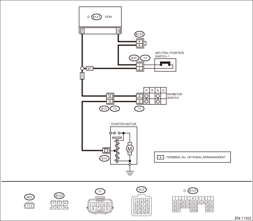
Wiring diagram:
Engine electrical system Engine Electrical System">
| STEP | CHECK | YES | NO |
1.CHECK SELECT CABLE.
Is there any fault in select cable?
Repair or adjust the select cable. Select Cable">
Diagnostic Procedure with Diagnostic Trouble Code (DTC) > DTC P0851 PARK/NEUTRAL SWITCH INPUT CIRCUIT LOW">Go to Step 2.
2.CHECK INPUT SIGNAL OF ECM.
1) Turn the ignition switch to ON.
2) Place the select lever in other than “P” range and “N” range.
3) Measure the voltage between ECM connector and chassis ground.
Connector & terminal
(B137) No. 16 (+) — Chassis ground (−):
Is the voltage 10 V or more?
Repair the poor contact of ECM connector.
Diagnostic Procedure with Diagnostic Trouble Code (DTC) > DTC P0851 PARK/NEUTRAL SWITCH INPUT CIRCUIT LOW">Go to Step 3.
3.CHECK HARNESS BETWEEN ECM AND TRANSMISSION HARNESS CONNECTOR.
1) Turn the ignition switch to OFF.
2) Disconnect the connector from ECM.
3) Disconnect the connectors from ECM and transmission harness connector (T3).
4) Measure the resistance between ECM connector and chassis ground.
Connector & terminal
(B137) No. 16 — Chassis ground:
Is the resistance 1 M? or more?
Diagnostic Procedure with Diagnostic Trouble Code (DTC) > DTC P0851 PARK/NEUTRAL SWITCH INPUT CIRCUIT LOW">Go to Step 4.
Repair the short circuit to ground in harness between ECM connector and transmission harness connector.
4.CHECK TRANSMISSION HARNESS CONNECTOR.
1) Disconnect the connector from inhibitor switch.
2) Measure the resistance between transmission harness connector and engine ground.
Connector & terminal
(T3) No. 16 — Engine ground:
Is the resistance 1 M? or more?
Replace the inhibitor switch. Inhibitor Switch">
Repair short circuit to ground in harness between transmission harness connector and inhibitor switch connector.
2. OUTLINE OF DIAGNOSIS
Detect the open or short circuit of neutral SW.
Judge as NG when the ECM neutral terminal input differs from the reception data from TCM.
3. EXECUTION CONDITION
Secondary Parameters | Execution condition |
Battery voltage | ≥ 10.9 V |
Starter relay feedback voltage | < Battery voltage ? 0.35 |
Data received from TCM | ≠ “P” range/“N” range |
4. GENERAL DRIVING CYCLE
Perform the diagnosis continuously in 2 seconds after starting the engine.
5. DIAGNOSTIC METHOD
If the duration of time while the following conditions are met is longer than the time indicated, judge as NG.
Malfunction Criteria | Threshold Value |
Neutral position switch voltage | ≤ Battery voltage ? 0.19 |
Time Needed for Diagnosis: 64 ms ? 100 time(s)
Malfunction Indicator Light Illumination: Illuminates when malfunction occurs in 2 continuous driving cycles.
6. MT MODEL
DTC detecting condition:
Detected when two consecutive driving cycles with fault occur.
Trouble symptom:
Improper idling
CAUTION:
After servicing or replacing faulty parts, perform Clear Memory Mode Clear Memory Mode > OPERATION">, and Inspection Mode Inspection Mode > PROCEDURE">.
Wiring diagram:
Engine electrical system Engine Electrical System">
| STEP | CHECK | YES | NO |
1.CHECK INPUT SIGNAL OF ECM.
1) Turn the ignition switch to ON.
2) Place the gear shift lever in a position other than neutral.
3) Measure the voltage between ECM connector and chassis ground.
Connector & terminal
(B137) No. 16 (+) — Chassis ground (−):
Is the voltage 10 V or more?
Repair the poor contact of ECM connector.
Diagnostic Procedure with Diagnostic Trouble Code (DTC) > DTC P0851 PARK/NEUTRAL SWITCH INPUT CIRCUIT LOW">Go to Step 2.
2.CHECK HARNESS BETWEEN ECM AND NEUTRAL POSITION SWITCH 1 CONNECTOR.
1) Turn the ignition switch to OFF.
2) Disconnect the connector from ECM.
3) Disconnect the connector from neutral position switch 1.
4) Measure the resistance between ECM connector and chassis ground.
Connector & terminal
(B137) No. 16 — Chassis ground:
Is the resistance 1 M? or more?
Replace the neutral position switch 1. Switches and Harness">
Repair the short circuit to ground in harness between ECM connector and neutral position switch 1 connector.
7. OUTLINE OF DIAGNOSIS
Detect the open or short circuit of neutral SW.
Judge as NG when there is no change in the neutral SW even if the driving shift was applied. (There is neutral SW ON/OFF inversion from the vehicle speed and engine speed.)
8. EXECUTION CONDITION
Secondary parameters | Execution condition |
Battery voltage | ≥ 10.9 V |
The number of driving condition change from a) to b) | = 3 time(s) |
a) | |
Vehicle speed | ≤ 0 km/h (0 MPH) |
and | |
Engine speed |
≥ 550 rpm and ≤ 850 rpm |
b) | |
Vehicle speed | ≥ 64 km/h (39.8 MPH) |
and | |
Engine speed |
≥ 1550 rpm and ≤ 2100 rpm |
9. GENERAL DRIVING CYCLE
Perform the diagnosis continuously in 2 seconds after starting the engine.
10. DIAGNOSTIC METHOD
Judge NG when the malfunction criteria below are completed determined times or more after the neutral SW change.
Malfunction Criteria | Threshold Value |
Neutral switch output voltage | ≤ Battery voltage ? 0.19 V |
Time needed for diagnosis: 3 time(s)
Malfunction indicator light illumination: Illuminates when malfunction occurs in 2 continuous driving cycles.

 Dtc p219a bank 1 air-fuel ratio imbalance
ENGINE (DIAGNOSTICS)(H4DO) > Diagnostic Procedure with Diagnostic Trouble Code (DTC)DTC P219A BANK 1 AIR-FUEL RATIO IMBALANCEDTC detecting condition:Detected when two consecutive driving cycles wit ...
Other materials:
Airflow mode selection
To select the airflow mode:
Type A, B and C: Turn the airflow mode
selection dial.
Type D: Press the airflow mode selection
button.
To select the defrost mode:
Type A and B: Turn the airflow mode
selection dial.
Type C and D: Press the defroster button.
Airflow modes are as follows. ...
Removal
REAR SUSPENSION > Rear Lateral LinkREMOVAL1. Disconnect the ground cable from battery. NOTE">2. Lift up the vehicle, and then remove the rear wheels.3. Remove the sensor assembly - headlight beam leveler. (Model with auto headlight beam leveler, left side only)CAUTION:Do not apply impact ...
Continuously variable transmission features
The continuously variable transmission is
electronically controlled and provides an
infinite number of forward speeds and 1
reverse speed. It also has a manual mode.
NOTE
When the engine coolant temperature
is still low, the transmission will
upshift or downshift at higher engine
speed ...
