Subaru Crosstrek Service Manual: Dtc p0843 transmission fluid pressure sensor/switch "a" circuit high
CONTINUOUSLY VARIABLE TRANSMISSION (DIAGNOSTICS) > Diagnostic Procedure with Diagnostic Trouble Code (DTC)
DTC P0843 TRANSMISSION FLUID PRESSURE SENSOR/SWITCH "A" CIRCUIT HIGH
DTC detecting condition:
Immediately at fault recognition
Trouble symptom:
Shift characteristics malfunction
CAUTION:
Use the check board when measuring the TCM terminal voltage and resistance.
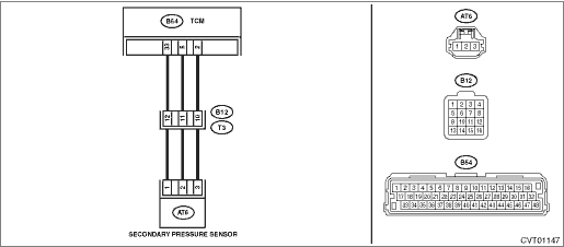
Wiring diagram:
CVT control system CVT Control System">

| STEP | CHECK | YES | NO |
1.CHECK INPUT SIGNAL FOR TCM.
1) Start the engine.
2) Warm up until the ATF temperature reaches to 40 — 70°C (104 — 158°F).
3) Depress the brake pedal, and shift the select lever to “D” range.
4) Shift the select lever to “P” range.
5) Stabilize the engine speed at idle.
6) Read the data of «Actual Secondary Pressure» using Subaru Select Monitor.
Is the «Actual Secondary Pressure» 0.5 — 1.5 MPa?
Check for poor contact of connector.
Diagnostic Procedure with Diagnostic Trouble Code (DTC) > DTC P0843 TRANSMISSION FLUID PRESSURE SENSOR/SWITCH "A" CIRCUIT HIGH">Go to Step 2.
2.CHECK HARNESS.
1) Turn the ignition switch to OFF.
2) Disconnect the TCM connector.
3) Disconnect the transmission connector.
4) Turn the ignition switch to ON.
5) Measure the voltage between TCM connector and chassis ground.
Connector & terminal
(B54) No. 5 (+) — Chassis ground (−):
(B54) No. 33 (+) — Chassis ground (−):
Is the voltage approx. 0 V?
Diagnostic Procedure with Diagnostic Trouble Code (DTC) > DTC P0843 TRANSMISSION FLUID PRESSURE SENSOR/SWITCH "A" CIRCUIT HIGH">Go to Step 3.
Repair the short circuit of harness.
3.CHECK HARNESS.
1) Turn the ignition switch to OFF.
2) Measure the resistance between TCM connector terminals.
Connector & terminal
(B54) No. 5 — (B54) No. 33:
Is the resistance less than 1 ??
Repair the short circuit of harness.
Diagnostic Procedure with Diagnostic Trouble Code (DTC) > DTC P0843 TRANSMISSION FLUID PRESSURE SENSOR/SWITCH "A" CIRCUIT HIGH">Go to Step 4.
4.CHECK TRANSMISSION HARNESS.
1) Disconnect the secondary pressure sensor connector.
2) Turn the ignition switch to ON.
3) Measure the voltage between transmission connector and chassis ground.
Connector & terminal
(T3) No. 11 (+) — Chassis ground (−):
(T3) No. 12 (+) — Chassis ground (−):
Is the voltage approx. 0 V?
Diagnostic Procedure with Diagnostic Trouble Code (DTC) > DTC P0843 TRANSMISSION FLUID PRESSURE SENSOR/SWITCH "A" CIRCUIT HIGH">Go to Step 5.
Repair the short circuit of harness.
5.CHECK TRANSMISSION HARNESS.
1) Turn the ignition switch to OFF.
2) Measure the resistance between transmission connector terminals.
Connector & terminal
(T3) No. 11 — (T3) No. 12:
Is the resistance less than 1 ??
Repair the short circuit of harness.
Diagnostic Procedure with Diagnostic Trouble Code (DTC) > DTC P0843 TRANSMISSION FLUID PRESSURE SENSOR/SWITCH "A" CIRCUIT HIGH">Go to Step 6.
6.CHECK POWER SUPPLY FOR SECONDARY PRESSURE SENSOR.
1) Connect the TCM connector.
2) Connect the transmission connector.
3) Turn the ignition switch to ON.
4) Measure the voltage between secondary pressure sensor connector terminals.
Connector & terminal
(AT6) No. 1 (+) — (AT6) No. 3 (−):
Is the voltage 4.5 V or more?
Replace the secondary pressure sensor. Secondary Pressure Sensor"> If the replacement of the sensor do not eliminate the malfunction, replace the TCM. Transmission Control Module (TCM)">
Check for poor contact of connector, and if no fault is found, replace the TCM. Transmission Control Module (TCM)">
1. OUTLINE OF DIAGNOSIS
• Detect short circuit to power supply or open circuit of the transmission line pressure sensor 5 V system.
• Judge as NG if the voltage detected by the transmission line pressure sensor is higher than the predetermined value.
2. EXECUTION CONDITION
Secondary Parameters | Execution condition |
12 V battery system voltage | ≥ 9 V |
3. DIAGNOSTIC METHOD
If the duration of time while the following conditions are met is longer than the time indicated, judge as NG.
Malfunction Criteria | Threshold Value |
Measured line pressure sensor input voltage | > 4.883 V |
(Line pressure) | (> 8200 kPa) |
Time Needed for Diagnosis: 1.5 seconds
Malfunction Indicator Light Illumination: Illuminates as soon as a malfunction occurs.
 Dtc p0842 transmission fluid pressure sensor/switch "a" circuit low
CONTINUOUSLY VARIABLE TRANSMISSION (DIAGNOSTICS) > Diagnostic Procedure with Diagnostic Trouble Code (DTC)DTC P0842 TRANSMISSION FLUID PRESSURE SENSOR/SWITCH "A" CIRCUIT LOWDTC detecting ...
 Dtc p0890 tcm power relay sense circuit low
CONTINUOUSLY VARIABLE TRANSMISSION (DIAGNOSTICS) > Diagnostic Procedure with Diagnostic Trouble Code (DTC)DTC P0890 TCM POWER RELAY SENSE CIRCUIT LOWDTC detecting condition:Immediately at fault rec ...
Other materials:
Selecting a station from the list (if equipped)
A station list can be displayed.
1. Touch the tab.
2. Touch the tab and the station
list will
appear.
3. Select the desired station.
Update the station list
Touch the "Update Station List" key on the
station list screen and the following screen
will be displayed.
...
Viewing range on the screen
CAUTION
The range that can be viewed with
the rear view camera is limited.
Always be sure to check with your
eyes when moving backward and
proceed slowly.
Range of view
Range of view
Image from camera
The area from the rear end of the bumper
can be viewed. Areas at both ends ...
Windshield wiper blade assembly
1. Raise the wiper arm off the windshield.
1) Stopper
2. Remove the wiper blade assembly by
holding its pivot area and pushing it in the
direction shown by the arrow while depressing
the wiper blade stopper.
3. Install the wiper blade assembly to the
wiper arm. Make sure that it locks i ...
