Subaru Crosstrek Service Manual: Dtc p060b internal control module a/d processing performance
ENGINE (DIAGNOSTICS)(H4DO) > Diagnostic Procedure with Diagnostic Trouble Code (DTC)
DTC P060B INTERNAL CONTROL MODULE A/D PROCESSING PERFORMANCE
NOTE:
For the diagnostic procedure, refer to DTC P0606. Diagnostic Procedure with Diagnostic Trouble Code (DTC) > DTC P0606 CONTROL MODULE PROCESSOR">
1. OUTLINE OF DIAGNOSIS
Judge as NG when any one of the followings is established.
(1) If the input amplifier circuit of throttle position sensor 1 is abnormal (quadruple amplification problem).
(2) If the A/D converter operation is abnormal (ADC malfunction).
2. COMPONENT DESCRIPTION
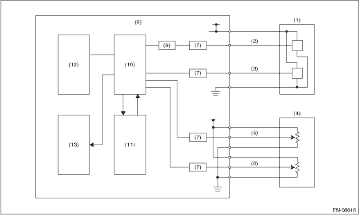
(1) | Throttle position sensor | (6) | Accelerator pedal position sensor 2 | (10) | CPU |
(2) | Throttle position sensor 1 | (7) | I/F circuit | (11) | Monitoring IC |
(3) | Throttle position sensor 2 | (8) | Amplifier circuit | (12) | EEPROM |
(4) | Accelerator pedal position sensor | (9) | Engine control module (ECM) | (13) | Output IC |
(5) | Accelerator pedal position sensor 1 |
3. EXECUTION CONDITION
Secondary Parameters | Execution condition |
Battery voltage | ≥ 6 V |
Target voltage | = 0 V |
Secondary Parameters | Execution condition |
Battery voltage | ≥ 6 V |
Target voltage | = 5 V |
4. GENERAL DRIVING CYCLE
Always perform the diagnosis continuously.
5. DIAGNOSTIC METHOD
Diagnosis 1
Judge as NG when the following conditions are established.
Malfunction Criteria | Threshold Value |
Actual voltage | > 0.01953125 V |
Time Needed for Diagnosis: 200 ms
Diagnosis 2
Judge as NG when the following conditions are established.
Malfunction Criteria | Threshold Value |
Actual voltage | > 4.979248047 V |
Time Needed for Diagnosis: 200 ms
Malfunction Indicator Light Illumination: Illuminates as soon as a malfunction occurs.
 Dtc p060a internal control module monitoring processor performance
ENGINE (DIAGNOSTICS)(H4DO) > Diagnostic Procedure with Diagnostic Trouble Code (DTC)DTC P060A INTERNAL CONTROL MODULE MONITORING PROCESSOR PERFORMANCENOTE:For the diagnostic procedure, refer to DTC ...
 Dtc p0616 starter relay "a" circuit low
ENGINE (DIAGNOSTICS)(H4DO) > Diagnostic Procedure with Diagnostic Trouble Code (DTC)DTC P0616 STARTER RELAY "A" CIRCUIT LOWDTC detecting condition:Immediately at fault recognitionCAUTION: ...
Other materials:
Intake and exhaust valve Specification
MECHANICAL(H4DO) > Intake and Exhaust ValveSPECIFICATIONRefer to “Cylinder Head” for removal and installation procedures of the intake and exhaust valves. Cylinder Head > REMOVAL"> Cylinder Head > INSTALLATION"> ...
Installation
MECHANICAL(H4DO) > CamshaftINSTALLATION1. CAMSHAFT RHThe camshaft RH and cam carrier are designed as installing as a unit. Refer to “Cam Carrier” for installation procedures of camshaft RH. Cam Carrier > ASSEMBLY"> Cam Carrier > INSTALLATION">2. CAMSHAFT LHThe ...
Disassembly
DRIVE SHAFT SYSTEM > Rear Drive ShaftDISASSEMBLY1. Remove the outer race (DOJ) from the shaft assembly.CAUTION:Be careful not to damage the boot.(1) Using a flat tip screwdriver or pliers, loosen the boot band on the large end of boot (DOJ).CAUTION:Be careful not to damage the boot.(2) Remove the ...
