Subaru Crosstrek Service Manual: Dtc p050a cold start idle control system performance
ENGINE (DIAGNOSTICS)(H4DO) > Diagnostic Procedure with Diagnostic Trouble Code (DTC)
DTC P050A COLD START IDLE CONTROL SYSTEM PERFORMANCE
DTC detecting condition:
Detected when two consecutive driving cycles with fault occur.
Trouble symptom:
• Engine keeps running at higher speed than specified idle speed.
• Engine keeps running at a lower speed than the specified idle speed.
• Engine stall
CAUTION:
After servicing or replacing faulty parts, perform Clear Memory Mode Clear Memory Mode > OPERATION"> , and Inspection Mode Inspection Mode > PROCEDURE">.
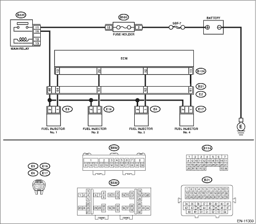
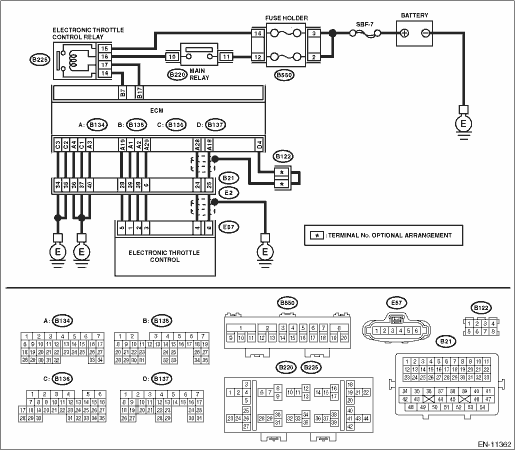
Wiring diagram:
Engine electrical system Engine Electrical System">
| STEP | CHECK | YES | NO |
1.CHECK FOR ANY OTHER DTC ON DISPLAY.
Is any other DTC displayed?
Check the appropriate DTC using the “List of Diagnostic Trouble Code (DTC)”. List of Diagnostic Trouble Code (DTC)">
Diagnostic Procedure with Diagnostic Trouble Code (DTC) > DTC P050A COLD START IDLE CONTROL SYSTEM PERFORMANCE">Go to Step 2.
2.CHECK ENGINE OIL.
Is there a proper amount of engine oil?
Diagnostic Procedure with Diagnostic Trouble Code (DTC) > DTC P050A COLD START IDLE CONTROL SYSTEM PERFORMANCE">Go to Step 3.
Replace engine oil. Engine Oil > REPLACEMENT">
3.CHECK EXHAUST SYSTEM.
Are there holes or loose bolts on exhaust system?
Repair the exhaust system.
Diagnostic Procedure with Diagnostic Trouble Code (DTC) > DTC P050A COLD START IDLE CONTROL SYSTEM PERFORMANCE">Go to Step 4.
4.CHECK AIR INTAKE SYSTEM.
Are there holes, loose bolts or disconnection of hose on air intake system?
Repair the air intake system.
Diagnostic Procedure with Diagnostic Trouble Code (DTC) > DTC P050A COLD START IDLE CONTROL SYSTEM PERFORMANCE">Go to Step 5.
5.CHECK FUEL PRESSURE.
WARNING:
Place “NO OPEN FLAMES” signs near the working area.
CAUTION:
Be careful not to spill fuel.
Measure the fuel pressure. Fuel Pressure > INSPECTION">
CAUTION:
Release fuel pressure before removing the fuel pressure gauge.
Is the measured value 340 — 400 kPa (3.5 — 4.1 kg/cm2, 49 — 58 psi)?
Diagnostic Procedure with Diagnostic Trouble Code (DTC) > DTC P050A COLD START IDLE CONTROL SYSTEM PERFORMANCE">Go to Step 6.
Check the fuel pump and fuel delivery line. Fuel Pump > INSPECTION"> Fuel Delivery and Evaporation Lines > INSPECTION">
6.CHECK ENGINE COOLANT TEMPERATURE SENSOR.
1) Start the engine and warm up completely.
2) Read the value of «Coolant Temp.» using the Subaru Select Monitor or a general scan tool.
NOTE:
• Subaru Select Monitor
For detailed operation procedures, refer to “Current Data Display For Engine”. Subaru Select Monitor">
• General scan tool
For detailed operation procedures, refer to the general scan tool operation manual.
Is the value of «Coolant Temp.» 75°C (167°F) or more?
Diagnostic Procedure with Diagnostic Trouble Code (DTC) > DTC P050A COLD START IDLE CONTROL SYSTEM PERFORMANCE">Go to Step 7.
Replace the engine coolant temperature sensor. Engine Coolant Temperature Sensor">
7.CHECK MASS AIR FLOW AND INTAKE AIR TEMPERATURE SENSOR.
1) Start the engine and warm up engine until coolant temperature is higher than 75°C (167°F).
2) For CVT models, set the select lever to “P” range or “N” range, and for MT models, place the gear shift lever in the neutral position.
3) Turn the A/C switch to OFF.
4) Turn all the accessory switches to OFF.
5) Read the value of «Mass Air Flow» using the Subaru Select Monitor or a general scan tool.
NOTE:
• Subaru Select Monitor
For detailed operation procedures, refer to “Current Data Display For Engine”. Subaru Select Monitor">
• General scan tool
For detailed operation procedures, refer to the general scan tool operation manual.
Is the value of «Mass Air Flow» 2.0 — 5.0 g/s (0.26 — 0.66 lb/m)?
Diagnostic Procedure with Diagnostic Trouble Code (DTC) > DTC P050A COLD START IDLE CONTROL SYSTEM PERFORMANCE">Go to Step 8.
Replace the mass air flow and intake air temperature sensor. Mass Air Flow and Intake Air Temperature Sensor">
8.CHECK MASS AIR FLOW AND INTAKE AIR TEMPERATURE SENSOR.
1) Start the engine and warm up engine until coolant temperature is higher than 75°C (167°F).
2) For CVT models, set the select lever to “P” range or “N” range, and for MT models, place the gear shift lever in the neutral position.
3) Turn the A/C switch to OFF.
4) Turn all the accessory switches to OFF.
5) Open the front hood.
6) Measure the ambient temperature.
7) Read the value of «Intake Air Temp.» using the Subaru Select Monitor or a general scan tool.
NOTE:
• Subaru Select Monitor
For detailed operation procedures, refer to “Current Data Display For Engine”. Subaru Select Monitor">
• General scan tool
For detailed operation procedures, refer to the general scan tool operation manual.
Subtract ambient temperature from «Intake Air Temp.». Is the obtained value −10 — 50°C (−18 — 90°F)?
Diagnostic Procedure with Diagnostic Trouble Code (DTC) > DTC P050A COLD START IDLE CONTROL SYSTEM PERFORMANCE">Go to Step 9.
Check the mass air flow and intake air temperature sensor. Mass Air Flow and Intake Air Temperature Sensor">
9.CHECK OUTPUT SIGNAL OF ECM.
1) Turn the ignition switch to ON.
2) Measure the voltage between ECM and chassis ground on faulty cylinders.
Connector & terminal
#1 (B134) No. 12 (+) — Chassis ground (−):
#2 (B134) No. 22 (+) — Chassis ground (−):
#3 (B134) No. 32 (+) — Chassis ground (−):
#4 (B134) No. 13 (+) — Chassis ground (−):
Is the voltage 10 V or more?
Diagnostic Procedure with Diagnostic Trouble Code (DTC) > DTC P050A COLD START IDLE CONTROL SYSTEM PERFORMANCE">Go to Step 14.
Diagnostic Procedure with Diagnostic Trouble Code (DTC) > DTC P050A COLD START IDLE CONTROL SYSTEM PERFORMANCE">Go to Step 10.
10.CHECK HARNESS BETWEEN ECM AND FUEL INJECTOR CONNECTOR.
1) Turn the ignition switch to OFF.
2) Disconnect the connector from fuel injector on faulty cylinders.
3) Measure the resistance between fuel injector connector and engine ground on faulty cylinders.
Connector & terminal
#1 (E5) No. 1 — Engine ground:
#2 (E16) No. 1 — Engine ground:
#3 (E6) No. 1 — Engine ground:
#4 (E17) No. 1 — Engine ground:
Is the resistance 1 M? or more?
Diagnostic Procedure with Diagnostic Trouble Code (DTC) > DTC P050A COLD START IDLE CONTROL SYSTEM PERFORMANCE">Go to Step 11.
Repair the short circuit to ground in harness between ECM connector and fuel injector connector.
11.CHECK HARNESS BETWEEN ECM AND FUEL INJECTOR CONNECTOR.
Measure the resistance of harness between ECM and fuel injector connector on faulty cylinders.
Connector & terminal
#1 (B134) No. 12 — (E5) No. 1:
#2 (B134) No. 22 — (E16) No. 1:
#3 (B134) No. 32 — (E6) No. 1:
#4 (B134) No. 13 — (E17) No. 1:
Is the resistance less than 1 ??
Diagnostic Procedure with Diagnostic Trouble Code (DTC) > DTC P050A COLD START IDLE CONTROL SYSTEM PERFORMANCE">Go to Step 12.
Repair the harness and connector.
NOTE:
In this case, repair the following item:
• Open circuit in harness between ECM connector and fuel injector connector
• Poor contact of coupling connector
12.CHECK FUEL INJECTOR.
Measure the resistance between fuel injector terminals on faulty cylinder.
Terminals
No. 1 — No. 2:
Is the resistance 5 — 20 ??
Diagnostic Procedure with Diagnostic Trouble Code (DTC) > DTC P050A COLD START IDLE CONTROL SYSTEM PERFORMANCE">Go to Step 13.
Replace the faulty fuel injector. Fuel Injector">
13.CHECK POWER SUPPLY LINE.
1) Turn the ignition switch to ON.
2) Measure the voltage between fuel injector and engine ground on faulty cylinders.
Connector & terminal
#1 (E5) No. 2 (+) — Engine ground (−):
#2 (E16) No. 2 (+) — Engine ground (−):
#3 (E6) No. 2 (+) — Engine ground (−):
#4 (E17) No. 2 (+) — Engine ground (−):
Is the voltage 10 V or more?
Repair the poor contact of all connectors in fuel injector circuit.
Repair the harness and connector.
NOTE:
In this case, repair the following item:
• Open circuit in harness between the main relay connector and fuel injector connector on faulty cylinders
• Poor contact of coupling connector
• Poor contact of main relay connector
14.CHECK HARNESS BETWEEN ECM AND FUEL INJECTOR CONNECTOR.
1) Turn the ignition switch to OFF.
2) Disconnect the connector from fuel injector on faulty cylinders.
3) Turn the ignition switch to ON.
4) Measure the voltage between ECM and chassis ground on faulty cylinders.
Connector & terminal
#1 (B134) No. 12 (+) — Chassis ground (−):
#2 (B134) No. 22 (+) — Chassis ground (−):
#3 (B134) No. 32 (+) — Chassis ground (−):
#4 (B134) No. 13 (+) — Chassis ground (−):
Is the voltage 10 V or more?
Repair the short circuit to power in harness between ECM connector and fuel injector.
Diagnostic Procedure with Diagnostic Trouble Code (DTC) > DTC P050A COLD START IDLE CONTROL SYSTEM PERFORMANCE">Go to Step 15.
15.CHECK FUEL INJECTOR.
1) Turn the ignition switch to OFF.
2) Measure the resistance between fuel injector terminals on faulty cylinder.
Terminals
No. 1 — No. 2:
Is the resistance 5 — 20 ??
Diagnostic Procedure with Diagnostic Trouble Code (DTC) > DTC P050A COLD START IDLE CONTROL SYSTEM PERFORMANCE">Go to Step 16.
Replace the faulty fuel injector. Fuel Injector">
16.CHECK INSTALLATION CONDITION OF CAMSHAFT POSITION SENSOR/CRANKSHAFT POSITION SENSOR.
Is the camshaft position sensor or crankshaft position sensor loosely installed?
Tighten the camshaft position sensor or crankshaft position sensor. Camshaft Position Sensor > INSTALLATION"> Crankshaft Position Sensor > INSTALLATION">
Diagnostic Procedure with Diagnostic Trouble Code (DTC) > DTC P050A COLD START IDLE CONTROL SYSTEM PERFORMANCE">Go to Step 17.
17.CHECK CRANKSHAFT POSITION SENSOR PLATE.
Is the crankshaft position sensor plate rusted or does it have broken teeth?
Replace the crankshaft position sensor plate. Cylinder Block">
Diagnostic Procedure with Diagnostic Trouble Code (DTC) > DTC P050A COLD START IDLE CONTROL SYSTEM PERFORMANCE">Go to Step 18.
18.CHECK INSTALLATION CONDITION OF TIMING CHAIN.
Turn the crankshaft using ST, and align the alignment mark on crank sprocket with alignment mark on cylinder block.
Is the timing chain dislocated from its proper position?
Correct the installation condition of timing chain. Timing Chain Assembly">
Diagnostic Procedure with Diagnostic Trouble Code (DTC) > DTC P050A COLD START IDLE CONTROL SYSTEM PERFORMANCE">Go to Step 19.
19.CHECK ELECTRONIC THROTTLE CONTROL RELAY.
1) Turn the ignition switch to OFF.
2) Remove the electronic throttle control relay.
3) Connect the battery to terminals No. 16 and No. 17 of electronic throttle control relay.
4) Measure the resistance between electronic throttle control relay terminals.
Terminals
No. 14 — No. 15:
Is the resistance less than 1 ??
Diagnostic Procedure with Diagnostic Trouble Code (DTC) > DTC P050A COLD START IDLE CONTROL SYSTEM PERFORMANCE">Go to Step 20.
Replace the electronic throttle control relay. Electronic Throttle Control Relay">
20.CHECK POWER SUPPLY OF ELECTRONIC THROTTLE CONTROL RELAY.
Measure the voltage between electronic throttle control relay connector and chassis ground.
Connector & terminal
(B225) No. 15 (+) — Chassis ground (−):
Is the voltage 10 V or more?
Diagnostic Procedure with Diagnostic Trouble Code (DTC) > DTC P050A COLD START IDLE CONTROL SYSTEM PERFORMANCE">Go to Step 21.
Repair the open or short to ground in the power supply circuit.
21.CHECK HARNESS BETWEEN ECM AND ELECTRONIC THROTTLE CONTROL RELAY CONNECTOR.
1) Disconnect the connector from ECM.
2) Turn the ignition switch to ON.
3) Measure the voltage between electronic throttle control relay connector and chassis ground.
Connector & terminal
(B225) No. 17 (+) — Chassis ground (−):
Is the voltage 10 V or more?
Repair the short circuit to power in the harness between ECM connector and electronic throttle control relay connector.
Diagnostic Procedure with Diagnostic Trouble Code (DTC) > DTC P050A COLD START IDLE CONTROL SYSTEM PERFORMANCE">Go to Step 22.
22.CHECK HARNESS BETWEEN ECM AND ELECTRONIC THROTTLE CONTROL RELAY CONNECTOR.
1) Turn the ignition switch to OFF.
2) Measure the resistance between electronic throttle control relay connector and chassis ground.
Connector & terminal
(B225) No. 14 — Chassis ground:
(B225) No. 17 — Chassis ground:
Is the resistance 1 M? or more?
Diagnostic Procedure with Diagnostic Trouble Code (DTC) > DTC P050A COLD START IDLE CONTROL SYSTEM PERFORMANCE">Go to Step 23.
Repair the short circuit to ground in harness between ECM connector and electronic throttle control relay connector.
23.CHECK HARNESS BETWEEN ECM AND ELECTRONIC THROTTLE CONTROL RELAY CONNECTOR.
Measure the resistance of harness between ECM connector and electronic throttle control relay connector.
Connector & terminal
(B135) No. 17 — (B225) No. 17:
(B135) No. 7 — (B225) No. 14:
Is the resistance less than 1 ??
Diagnostic Procedure with Diagnostic Trouble Code (DTC) > DTC P050A COLD START IDLE CONTROL SYSTEM PERFORMANCE">Go to Step 24.
Repair the open circuit in harness between ECM connector and electronic throttle control relay connector.
24.CHECK HARNESS BETWEEN ECM AND ELECTRONIC THROTTLE CONTROL CONNECTOR.
1) Turn the ignition switch to OFF.
2) Disconnect the connector from ECM.
3) Disconnect the connectors from electronic throttle control.
4) Measure the resistance between ECM connector and chassis ground.
Connector & terminal
(B134) No. 19 — Chassis ground:
(B134) No. 18 — Chassis ground:
(B134) No. 18 — (B137) No. 4:
(B134) No. 28 — Chassis ground:
(B134) No. 28 — (B137) No. 4:
Is the resistance 1 M? or more?
Diagnostic Procedure with Diagnostic Trouble Code (DTC) > DTC P050A COLD START IDLE CONTROL SYSTEM PERFORMANCE">Go to Step 25.
Repair the ground short circuit of harness between ECM connector and electronic throttle control connector.
25.CHECK SHORT CIRCUIT INSIDE THE ECM.
1) Connect the connector to ECM.
2) Measure the resistance between electronic throttle control connector and engine ground.
Connector & terminal
(E57) No. 6 — Engine ground:
(E57) No. 4 — Engine ground:
Is the resistance 1 M? or more?
Diagnostic Procedure with Diagnostic Trouble Code (DTC) > DTC P050A COLD START IDLE CONTROL SYSTEM PERFORMANCE">Go to Step 26.
Repair the ground short circuit of harness between ECM connector and electronic throttle control connector. Replace the ECM if defective. Engine Control Module (ECM)">
26.CHECK HARNESS BETWEEN ECM AND ELECTRONIC THROTTLE CONTROL CONNECTOR.
1) Disconnect the connector from ECM.
2) Measure the resistance of harness between ECM connector and electronic throttle control connector.
Connector & terminal
(B134) No. 18 — (E57) No. 6:
(B134) No. 28 — (E57) No. 4:
(B134) No. 29 — (E57) No. 3:
Is the resistance less than 1 ??
Diagnostic Procedure with Diagnostic Trouble Code (DTC) > DTC P050A COLD START IDLE CONTROL SYSTEM PERFORMANCE">Go to Step 27.
 Dtc p0301 cylinder 1 misfire detected
ENGINE (DIAGNOSTICS)(H4DO) > Diagnostic Procedure with Diagnostic Trouble Code (DTC)DTC P0301 CYLINDER 1 MISFIRE DETECTEDNOTE:For the diagnostic procedure, refer to DTC P0304. Diagnostic Procedure ...

Other materials:
Warranties and maintenance
SUBARU warranties do not apply to
vehicle damage or malfunction caused
by trailer towing. If you use your vehicle to
tow a trailer, more frequent maintenance
will be required due to the additional load.
(Refer to "Maintenance schedule under
severe driving conditions" in the "Warranty
and Ma ...
Dtc u0402 invalid data received from tcm
LAN SYSTEM (DIAGNOSTICS) > Diagnostic Procedure with Diagnostic Trouble Code (DTC)DTC U0402 INVALID DATA RECEIVED FROM TCMDTC detecting condition:Received error data from TCM.Trouble symptom:Sport indicator light blinks.STEPCHECKYESNO1.CHECK PERFORMING OF BASIC DIAGNOSTIC PROCEDURE.Was the basic ...
Dtc b14eb intake door actuator stuck
HVAC SYSTEM (AUTO A/C) (DIAGNOSTICS) > Diagnostic Procedure with Diagnostic Trouble Code (DTC)DTC B14EB INTAKE DOOR ACTUATOR STUCKDTC detecting condition:• Intake door actuator is locked.• The potentiometer value of the actuator does not change.Trouble symptom:FRESH/RECIRC does not op ...
