Subaru Crosstrek Service Manual: Dtc p0222 throttle/pedal position sensor/switch "b" circuit low
ENGINE (DIAGNOSTICS)(H4DO) > Diagnostic Procedure with Diagnostic Trouble Code (DTC)
DTC P0222 THROTTLE/PEDAL POSITION SENSOR/SWITCH "B" CIRCUIT LOW
DTC detecting condition:
Immediately at fault recognition
Trouble symptom:
• Improper idling
• Poor driving performance
• Engine stall
CAUTION:
After servicing or replacing faulty parts, perform Clear Memory Mode Clear Memory Mode > OPERATION"> , and Inspection Mode Inspection Mode > PROCEDURE">.
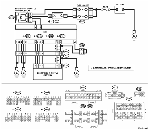
Wiring diagram:
Engine electrical system Engine Electrical System">
| STEP | CHECK | YES | NO |
1.CHECK HARNESS BETWEEN ECM AND ELECTRONIC THROTTLE CONTROL CONNECTOR.
1) Turn the ignition switch to OFF.
2) Disconnect the connector from ECM.
3) Disconnect the connectors from electronic throttle control.
4) Measure the resistance between ECM connector and chassis ground.
Connector & terminal
(B134) No. 19 — Chassis ground:
(B134) No. 28 — Chassis ground:
(B134) No. 28 — (B137) No. 4:
Is the resistance 1 M? or more?
Diagnostic Procedure with Diagnostic Trouble Code (DTC) > DTC P0222 THROTTLE/PEDAL POSITION SENSOR/SWITCH "B" CIRCUIT LOW">Go to Step 2.
Repair the ground short circuit of harness between ECM connector and electronic throttle control connector.
2.CHECK SHORT CIRCUIT INSIDE THE ECM.
1) Connect the connector to ECM.
2) Measure the resistance between electronic throttle control connector and engine ground.
Connector & terminal
(E57) No. 4 — Engine ground:
Is the resistance 1 M? or more?
Replace the electronic throttle control. Throttle Body">
Repair the ground short circuit of harness between ECM connector and electronic throttle control connector. Replace the ECM if defective. Engine Control Module (ECM)">
1. OUTLINE OF DIAGNOSIS
Detect the open or short circuit of throttle position sensor 2.
Judge as NG if out of specification.
2. COMPONENT DESCRIPTION
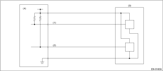
(1) | Throttle position sensor 1 signal | (3) | Throttle position sensor | (4) | Engine control module (ECM) |
(2) | Throttle position sensor 2 signal |
3. EXECUTION CONDITION
Secondary Parameters | Execution condition |
Battery voltage | ≥ 6 V |
4. GENERAL DRIVING CYCLE
Always perform the diagnosis continuously.
5. DIAGNOSTIC METHOD
If the duration of time while the following conditions are met is longer than the time indicated, judge as NG.
Malfunction Criteria | Threshold Value |
Sensor 2 input voltage | ≤ 1.133 V |
Time Needed for Diagnosis: 24 ms
Malfunction Indicator Light Illumination: Illuminates as soon as a malfunction occurs.
 Dtc p0204 cylinder 4 injector "a" circuit
ENGINE (DIAGNOSTICS)(H4DO) > Diagnostic Procedure with Diagnostic Trouble Code (DTC)DTC P0204 CYLINDER 4 INJECTOR "A" CIRCUITNOTE:For the diagnostic procedure, refer to DTC P0201. Diagno ...
 Dtc p0223 throttle/pedal position sensor/switch "b" circuit high
ENGINE (DIAGNOSTICS)(H4DO) > Diagnostic Procedure with Diagnostic Trouble Code (DTC)DTC P0223 THROTTLE/PEDAL POSITION SENSOR/SWITCH "B" CIRCUIT HIGHDTC detecting condition:Immediately at ...
Other materials:
Disassembly
MANUAL TRANSMISSION AND DIFFERENTIAL(5MT) > Reverse Check SleeveDISASSEMBLY1. Cover the reverse check sleeve with cloth, and remove the snap ring by using screwdriver.NOTE:If the snap ring is deformed or the spring repulsive force is not enough, replace with a new snap ring.(A)Snap ring2. Remove ...
Dtc p0202 cylinder 2 injector "a" circuit
ENGINE (DIAGNOSTICS)(H4DO) > Diagnostic Procedure with Diagnostic Trouble Code (DTC)DTC P0202 CYLINDER 2 INJECTOR "A" CIRCUITNOTE:For the diagnostic procedure, refer to DTC P0201. Diagnostic Procedure with Diagnostic Trouble Code (DTC) > DTC P0201 CYLINDER 1 INJECTOR "A" C ...
Installation
EXTERIOR BODY PANELS > Front FenderINSTALLATION1. Install each part in the reverse order of removal.CAUTION:• Install the bumper face - front so that the front end of the under cover (b) comes inside the bumper face - front (a), and the front end of the mud guard (c) comes outside the bumpe ...
