Subaru Crosstrek Service Manual: Dtc p0201 cylinder 1 injector "a" circuit
ENGINE (DIAGNOSTICS)(H4DO) > Diagnostic Procedure with Diagnostic Trouble Code (DTC)
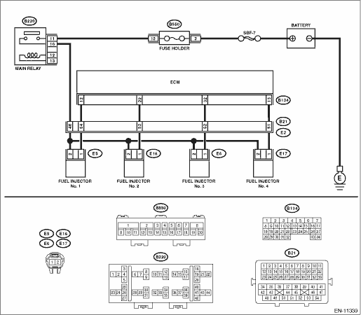
DTC P0201 CYLINDER 1 INJECTOR "A" CIRCUIT
DTC DETECTING CONDITION:
Immediately at fault recognition
TROUBLE SYMPTOM:
• Improper idling
• Poor driving performance
CAUTION:
After servicing or replacing faulty parts, perform Clear Memory Mode Clear Memory Mode > OPERATION"> , and Inspection Mode Inspection Mode > PROCEDURE">.
WIRING DIAGRAM:
Engine electrical system Engine Electrical System">
| STEP | CHECK | YES | NO |
1.CHECK POWER SUPPLY TO FUEL INJECTOR.
1) Turn the ignition switch to OFF.
2) Disconnect the connector from fuel injector.
3) Turn the ignition switch to ON.
4) Measure the voltage between fuel injector connector and the engine ground.
Connector & terminal
DTC P0201; (E5) No. 2 (+) — Engine ground (−):
DTC P0202; (E16) No. 2 (+) — Engine ground (−):
DTC P0203; (E6) No. 2 (+) — Engine ground (−):
DTC P0204; (E17) No. 2 (+) — Engine ground (−):
Is the voltage 10 V or more?
Diagnostic Procedure with Diagnostic Trouble Code (DTC) > DTC P0201 CYLINDER 1 INJECTOR "A" CIRCUIT">Go to Step 2.
Repair the harness and connector.
NOTE:
In this case, repair the following item:
• Open circuit in harness between main relay and fuel injector connector
• Poor contact of main relay connector
• Poor contact of coupling connector
2.CHECK HARNESS BETWEEN ECM AND FUEL INJECTOR CONNECTOR.
1) Turn the ignition switch to OFF.
2) Disconnect the connector from ECM.
3) Measure the resistance between fuel injector connector and engine ground.
Connector & terminal
DTC P0201; (E5) No. 1 — Engine ground:
DTC P0202; (E16) No. 1 — Engine ground:
DTC P0203; (E6) No. 1 — Engine ground:
DTC P0204; (E17) No. 1 — Engine ground:
Is the resistance 1 M? or more?
Diagnostic Procedure with Diagnostic Trouble Code (DTC) > DTC P0201 CYLINDER 1 INJECTOR "A" CIRCUIT">Go to Step 3.
Repair the short circuit to ground in harness between ECM connector and fuel injector connector.
3.CHECK HARNESS BETWEEN ECM AND FUEL INJECTOR CONNECTOR.
Measure the resistance of harness between ECM connector and fuel injector connector.
Connector & terminal
DTC P0201; (B134) No. 12 — (E5) No. 1:
DTC P0202; (B134) No. 22 — (E16) No. 1:
DTC P0203; (B134) No. 32 — (E6) No. 1:
DTC P0204; (B134) No. 13 — (E17) No. 1:
Is the resistance less than 1 ??
Diagnostic Procedure with Diagnostic Trouble Code (DTC) > DTC P0201 CYLINDER 1 INJECTOR "A" CIRCUIT">Go to Step 4.
Repair the harness and connector.
NOTE:
In this case, repair the following item:
• Open circuit in harness between ECM connector and fuel injector connector
• Poor contact of coupling connector
4.CHECK FUEL INJECTOR.
Measure the resistance between fuel injector terminals on the corresponding cylinder.
Terminals
No. 1 — No. 2:
Is the resistance 5 — 20 ??
Diagnostic Procedure with Diagnostic Trouble Code (DTC) > DTC P0201 CYLINDER 1 INJECTOR "A" CIRCUIT">Go to Step 5.
Replace the fuel injector. Fuel Injector">
5.CHECK FOR POOR CONTACT.
Check for poor contact of ECM connector.
Is there poor contact of ECM connector?
Repair the poor contact of ECM connector.
Diagnostic Procedure with Diagnostic Trouble Code (DTC) > DTC P0201 CYLINDER 1 INJECTOR "A" CIRCUIT">Go to Step 6.
6.CHECK FUEL INJECTOR OPERATION.
1) Connect all connectors.
2) Start the engine.
3) Check if the corresponding fuel injector emits operating sound.
NOTE:
Use a sound scope to check the operating sound.
Does the fuel injector emit operating sound?
Even if DTC is detected, the circuit has returned to a normal condition at this time. Reproduce the failure, and then perform the diagnosis again.
NOTE:
In this case, temporary poor contact of connector, temporary open or short circuit of harness may be the cause.
Repair the poor contact of fuel injector connector.
1. OUTLINE OF DIAGNOSIS
Based on the self-diagnostic result of the injector driving IC, judge the injector driving circuit as normal or abnormal.
Injector driving IC detects the status of “fuel remains injected” or “fuel is not injected” as a malfunction.
2. EXECUTION CONDITION
Secondary parameters | Execution condition |
Battery voltage | ≥ 10.9 V |
Elapsed time after starting the engine | > 1 s |
Engine speed | ≥ 500 rpm |
Injection status | Not during fuel cut |
3. GENERAL DRIVING CYCLE
Always perform the diagnosis continuously.
4. DIAGNOSTIC METHOD
Judge as NG when the following conditions are established.
Malfunction Criteria | Threshold Value |
Injector driving IC information | Trouble |
Time Needed for Diagnosis: 2560 ms
Malfunction Indicator Light Illumination: Illuminates as soon as a malfunction occurs.
 Dtc p0198 engine oil temperature sensor "a" circuit high
ENGINE (DIAGNOSTICS)(H4DO) > Diagnostic Procedure with Diagnostic Trouble Code (DTC)DTC P0198 ENGINE OIL TEMPERATURE SENSOR "A" CIRCUIT HIGHDTC detecting condition:Immediately at fault re ...
 Dtc p0202 cylinder 2 injector "a" circuit
ENGINE (DIAGNOSTICS)(H4DO) > Diagnostic Procedure with Diagnostic Trouble Code (DTC)DTC P0202 CYLINDER 2 INJECTOR "A" CIRCUITNOTE:For the diagnostic procedure, refer to DTC P0201. Diagno ...
Other materials:
Inspection
GLASS/WINDOWS/MIRRORS > Front Regulator and Motor AssemblyINSPECTION1. Disconnect the connector of the motor - front.2. Check the motor operation when battery voltage is applied between terminals of the motor - front connector.• LH sideTerminal No.Inspection conditionsStandard4 (+) — 1 (& ...
Coat hook
A coat hook is attached to the rear
passenger's hand grip.
WARNING
Obey the following instructions.
Do not hang coat hangers or
other hard or pointed objects on
the coat hooks. Hang clothing
directly on the coat hooks without
using hangers.
Before hanging clothing on the
coat ...
Removal
EXTERIOR/INTERIOR TRIM > Instrument Panel AssemblyREMOVALCAUTION:• Before handling the airbag system components, refer to “CAUTION” of “General Description” in “AIRBAG SYSTEM”. General Description > CAUTION">• Be careful not to damage th ...
